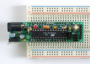
The Wince Cellar Controller is based on the Arduino. For this particular version, I’m using an Adafruit Boarduino
The boarduino is totally compatible with the Arduino, but some components have been replaced/eliminated to reduce the board size. This particular board is less than half the size of the standard Arduino. You need a special cable to program it, and once installed, all is required is a 7-24 volt power supply (or battery). The main advantage, for prototyping, is that you can install this small board directly on a prototyping board (breadboard) and test your idea without soldering and still are able to add extra parts to you circuit.
In nearly full testing regalia, this is how my project board looks:
I decided to add a display to the board. A two-line display costs less than 20$. In this picture, the humidity/temperature sensor is different from the one that I use for the final controller. This one has a long cable and will be used in a different project (Future – Beer Brewing Temperature Controller).
So, the first part of the project is as follows:
- Arduino/Boarduino on a breadboard
- Display
- Temperature/Humidity sensor
Schematic:
The display wiring is standard and easily found on the internet. The data sheet is here. There is a very good tutorial right here, on the Arduino.cc website, with very clear pin placement and Arduino programming examples.
The sensor is a HSM-20G. The datasheet is he here, and there is a very good discussion on the Arduino forum. You could chose any sensor, as long as you can get the specifications. I picked this one because it was available at my local shop (www.robotshop.ca)
 The humidity sensor is on the other side
The trick with the temperature sensor is knowing the calibration factor. You will have to write a routine to calculate the displayed temperature and humidity based on the reading coming in to a couple of analog pins on the Arduino. I your sensor is well designed, the manufacturer will have added some circuitry to output a linear voltage variation that can easily transformed into a calculated number using simple math and a few constants. If it is not linear, good luck. You’re on your own! Non linear (cheap) temperature sensors are easy to recognize because they usually only have two wires. They act as a variable resistance. The same sensors are used in better sensor boards, but additional circuitry provides a linear, compensated output. I would also guess that a sensor board that includes a humidity sensor will provide the additional parts, because relative humidity sensing is slightly more complicated.
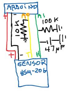
For this sensor, the suggested hook-up to the arduino includes a few components: 2 resistors and a capacitor. I don’t have enough knowledge in electronics to know if these components are really necessary or what their axact function is. Someone could post a quick explanation in the comments?
Here’s the circuit for the sensor:
After testing on the breadboard, I mounted the project permanently on a solder pcb board to be able to put it in a box.
The code:
/*
 This code will read from a variety of sensors
 and output to an LCD display.
 Requires the "LiquidCrystal Library" from the Arduino environment.

 The LiquidCrystal library works with all LCD displays that are
 compatible with the
 Hitachi HD44780 driver. There are many of them out there, and you
 can usually tell them by the 16-pin interface.


 The circuit:
 * LCD RS pin to digital pin 12
 * LCD Enable pin to digital pin 11
 * LCD D4 pin to digital pin 5
 * LCD D5 pin to digital pin 4
 * LCD D6 pin to digital pin 3
 * LCD D7 pin to digital pin 2
 * 10K resistor:
 * ends to +5V and ground
 * wiper to LCD VO pin (pin 3)

 Library originally added 18 Apr 2008
 by David A. Mellis
 library modified 5 Jul 2009
 by Limor Fried (http://www.ladyada.net)
 example added 9 Jul 2009
 by Tom Igoe
 modified 25 July 2009
 by David A. Mellis
 Code for temp and humid sensors (HSM-G20) by Robert Turenne 2011/3/2
 from http://sites.google.com/site/measuringstuff/more-sensor-examples#TOC-HSM-20G-Humidity-and-Temperature-Mi

 http://www.practicalusage.com
 http://www.arduino.cc/en/Tutorial/LiquidCrystal
 */

// include the library code:
#include <LiquidCrystal.h>

// initialize the library with the numbers of the interface pins
LiquidCrystal lcd(7, 8, 9, 10, 11, 12);
//int sensorPin = 0;    // select the input pin for the potentiometer
int ledPin = 13;      // select the pin for the LED
int sensorValue = 0;  // variable to store the value coming from the sensor
const byte nsum=10;
int humidityPin=1;
int Thgm20Pin=0;
unsigned int sensorValue2 = 0;  // variable to store the value coming from the sensor
unsigned int sensorValue3 = 0;  // variable to store the value coming from the sensor


void setup() {
 // set up the LCD's number of rows and columns:
 lcd.begin(16, 2);
 Serial.begin(9600);
 pinMode(ledPin, OUTPUT);

}

void loop() {
 //Read sensor values
 //works with an average of the last readings (i++)
 //Take successive readings (up to nsum)
 for (byte i=0;i<nsum;i++)
 {
 sensorValue2 += analogRead(humidityPin);
 sensorValue3 += analogRead(Thgm20Pin);
 }
 //Calculate Relative Humidity, using a constant
 //The curve from the datasheet is eq to
 // RH=31*volts-12
 //Since we have a 5 volts reference from the Arduino
 //and the analog is divided into 1024 values
 // RH=(31*(volts*5/1024)-12 or 0.1515 * volts - 12
 //First calculate the average of the last nsum readings
 int sensorValue2Avg=sensorValue2/nsum;
 float RH= 0.1515*sensorValue2Avg-12.0;

 //Calculate Temp using a slightly more complex formula
 //C = 281.583*1.0230^(1.0/R)*R^-0.1227 -150.6614
 int sensorValue3Avg=sensorValue3/nsum;
 // Again, 5 volts into 1024 intervals on the analog
 float Vt=(float) sensorValue3Avg*5.0/1023.0;
 // Using a little Ohm Law because of the 10K resistor
 float R=(5.0-Vt)*10.0/Vt;
 //Apply our curve fitting formula
 float TinC=281.583*pow(1.0230,(1.0/R))*pow(R,-0.1227)-150.6614;
 // Calculate temp in Farenheit
 float TinF=TinC*(9.0/5.0)+32;

 // print so serial port, for testing or data acquisition
 // Can be commented
 Serial.print(RH,0);
 Serial.println(" %RH");
 Serial.print(TinC,1);
 Serial.println(" deg C");
 Serial.print(TinF,1);
 Serial.println(" deg F");

 // Print to LCD
 // Set cursor to line 1, position 1
 // But we count from 0!
 lcd.setCursor(0,0);
 lcd.print("T1 ");
 lcd.print(TinC);
 // Set cursor on second line, position 1
 // Actually, line 1, position 0 !
 lcd.setCursor(0,1);
 lcd.print("H1 ");
 lcd.print(RH);

 sensorValue2=0;
 sensorValue3=0;
 sensorValue4=0;
 // Wait for 1 second
 delay(1000);
}


