Alesis Vortex: Firmware update 1.20 and Vyzex Patch Edit program available

Well, Alesis is listening to it’s users. They have just published a new firmware version for the Vortex.

Version 1.20:

  1. Allows compatibility with the Vyzex Vortex patch editor software
  2. Allows the pitch-bend wheel to be reversed
  3. Allows any pad to be set to “Panic Mode” (pad will send an “all-notes off” message)
  4. Allows a default volume message to be set for both the lower and upper keyboard zones of each patch

To upgrade, you have to download the file (Windows or Mac) from the Alesis site. The Windows file is an executable and will pretty much do everything for you, including finding the Vortex. Windows being Windows, it might not find the Vortex if it can’t see it. Check your ports. You will be asked to enter a name and email, but there is no validation.

While I wasn’t able to upgrade the firmware using my Mac (two different Macs, using three different configurations. So much for testing on a Mac, Alesis!) I had no problems using a Windows (Win7) computer. Some people have reported trouble on Windows 8.

Let’s look at the updated features:

1.   Alesis just made a Patch editor available. This is great news! Users have been requesting a Patch editor (and Patch Saver) since the Vortex came out. I have asked many times on their forum for different ways to access the storage area of the Vortex. I was told by the support person in charge of Vortex that it was not possible, even after he asked the tech people at Alesis. Although I was able to figure out a way to use a Sysex prompt to elicit a Sysex id sequence from the Vortex, all other communications to the instrument failed. I have also published a detailed user guide to explain in detail alternate ways to program the Vortex. That post was very popular. I thought about writing a Patch Editor myself, but not being able to read or write to the Vortex kind of killed that idea.

Well, I guess that’s what the new firmware allows now!

Vortex-Vizex image

Vortex Image appearing in Vyzex software
Probably copyright Psicraft, Alesis.

Let’s look at the actual Patch Editor:

First, you have to download the Patch Editor. This involves looking at the bottom of the alexis.com/vortex page for a link that looks like Yes! I am a Vortex owner and I want my free Vyzex Vortex patch editor softwareThat will take you to a page where you have to enter you name, email address and Vortex Serial Number. The name doesn’t matter but the email address does, since you will get an email with the actual link to the software. If you don’t remember where the Vortex Serial Number is (it’s on the back) or if you think that this is too much information to give Alesis anyway, a look at the JavaScript will let you know that the format of the Serial Number is: var regexp =/^BN1208[A-Z0-9]{9}$/; So, entering BN1208 followed by any 9 letter-or-digit combination (like BN1208123456789) will give you a valid serial number. There is no other validation.

You will receive an email with a link to the actual download page. The software zip file contains both Windows and Mac versions of the software. The link is valid for a limited time! (maybe 24 hours), so just go ahead and download. You can’t re-use an email/serial combination to resuscitate the link.

The software is written by a company called Psicraft (psicraft.com), which specialises in … Patch Editor development! The product offered by Alesis is from their Vyzex line, meaning that it is a standalone product made for a particular instrument. There is no mention of any deal with Alesis on the Psicraft site, even in their forum area. They mention Akai, M-Audio, Line6 and others, but not Alesis. This must be a very new deal between Psicraft and Alesis.

General impression: It works and looks good. Help files are available (except the “troubleshooting” file?) and they give a detailed explanation of the software functions. Installation is simple. It is definitely a much better way to program the Vortex than the standard, onboard method. Thanks, Alesis!

Post install operation might cause you problems. On a Mac, the program sends a “request for id” Sysex command on every Midi port available. If a Vortex is present, it will respond with a short Sysex sequence (effectively identifying itself). That’s pretty foolproof. The software will then read the configuration of every patch stored on the Vortex. On Windows, the program will not be able to access the Midi port if it is also used by other software. This is well explained in the Quick Start Guide installed with the software. Look at section 3: If running Windows, verify there are no USB MIDI driver conflicts between Vyzex Vortex and other software. That’s what happened to me when I launched Midi-Ox to try and sniff the Midi traffic between the Vortex and the computer.

Once the Vyzex software has found the Vortex and read the patches stored in the Vortex’s memory, you can edit every parameter with ease, using a pleasant (and exact) representation of the Vortex. Just read the user guide (also available on the Alesis site)(just enter any name/email) EDIT: Vortex is retired so read the Wireless Vortex user guide. Most applies to the Vortex.

2. Allows the pitch-bend wheel to be reversed

This can be done using the Vyzex software. I had a user ask me here if it was possible: it is now!

3. Allows any pad to be set to “Panic Mode” (pad will send an “all-notes off” message)

I have had regular bad luck with stuck notes using the Vortex. Most of the time, it’s because the Vortex is sending Midi commands with “Running Status” always On and no way to turn it off. Some hardware/software combinations have a problem with that. I guess I was not the only one complaining. Any pad can now be assigned a “Panic Button” function. Hopefully, it will send on both channels if required by the Split Keyboard configuration. It would be nice to also be able to turn Running Status Off.

4. Allows a default volume message to be set for both the lower and upper keyboard zones of each patch

The last firmware change will let you set a default volume for each part of the (split) keyboard. I really have no idea where this request comes from, and this looks like something very particular. But if you need it, it’s there.

Note: I will publish a technical post in a few days that explains the detailed communication sequence between the Vortex and the Vyzex software. Hint: It’s all Sysex, and definitely reproducible.

Posted in Music equipment, Vortex | Tagged | 10 Comments

MP-2 + MRe: Hacking the Alesis Vortex and using a Wireless Midi Transmitter

A two-project merge!

The Alesis Vortex needed a bit more… controls! So I decided to add a few sensors that would give me greater flexibility when playing. The Vortex is already quite capable, but my left hand was not “used” enough. Sure, there is a touch strip and a pitch-bend wheel at my finger tips. But I’m not a big fan of pitch-bend. Being a keyboard player, not a guitar player, having more “keys” for my left hand just makes more sense. I have seen keytar players “cross-under” the support strap to use their left hand on the (small) keyboard part. I have tried and it’s really uncomfortable because it puts the left wrist at a very odd angle. Since the keyboard part of the Vortex is only three octave long, my left wrist starts hurting as soon as I try that. Plus it looks dorky…     the keytar is bad enough by itself!

So, I decided to add a series of sensors for my left fingers to generate Midi commands. The Midi Processor (MP-2) creates the commands and merges them with the Vortex’s own Midi traffic. The MRe part then sends this data stream wirelessly to another Midi Processor connected to a computer.

Here’s a picture of the temporary hack prototype: (click on pictures)

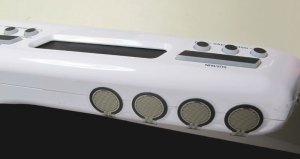
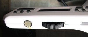
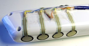
I have installed a series of (5) variable touch sensors where my left fingers would naturally rest when holding the Vortex. Four sensors are on the bottom and one is on top, near the Pitch-Bend wheel:

A cable (standard network patch cable (UTP)) is used to carry the signal from this end…

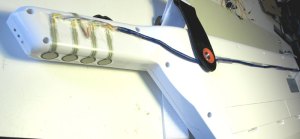
to this end: (there’s even a channel at the back of the Vortex!)

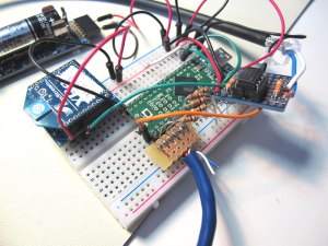
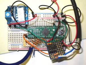
I’m combining the data from the sensors with the Midi data coming from the Vortex. I use a Teensy++ 2 for the prototype. It’s programmable in the Arduino environment, has a flexible port definition and is fast. The data is sent wirelessly using an XBee radio (see this post). I can operate all this using a 1.5 Volt battery and a voltage booster (Jeelab’s AA board) but the current draw is quite high (about 60 mA at 3.3 V, so well over 150 mA at the battery), so it’s better, and nearly as compact, using two (or three) AA batteries.

The top left shows the XBee, programmed to communicate with the micro-controller at 31250 Bps (MIDI). Only 3 wires are needed: + and GND (at 3.3Volts) and a connection to the Midi Out pin. On the right, a short Midi cable goes through an opto-coupler to the Midi In pin. The opto-coupler is needed more as a voltage/logic isolator (Midi operates at 5 volts and the micro-controller is using 3.3 volts in this setup) than a standard Midi isolator, but the wiring is the same. At the bottom left, the blue cable is tied to a series of pull-down resistors and each sensor connects to an analog pin. If I operate the Teensy at 5 volts, I have to add a voltage regulator to provide 3.3 volts to the XBee.

The program is divided into two parts. The first part is using the Arduino Midi Library and continuously reads data (if any) coming in from the Vortex. The data is echoed (Thru ON) directly to the Midi Out (and the XBee). The second part of the program is processing the sensor data. Globally, if the thumb sensor is active, the finger sensor data is providing an analog reading that is used to calculate velocity. I use the thumb sensor as a “gate” because the sensors are very sensitive and will send data at the slightest touch. A note (or any Midi commands) is associated to each sensor. The data is transformed into a Midi command (note + velocity) and merged into the Midi traffic from the Vortex. The merging is done using the Midi Library. By the way, the sensors are programmed for velocity, not just ON/OFF, and can provide POLY or Channel Aftertouch!

A video demo is coming.

(No Vortex was hurt during this hack)

Posted in Arduino, Electronics, MP, MP-2, Music equipment, Vortex | 3 Comments

MRe-2: A demo

I have decided to try the MRe-2 in a real setting. So I hooked up my keyboard and recorded a demo.

It was done using Ableton Live 9. The trick was to setup 2 midi loops (using clips). The first one is used to loop the riff that plays after the intro. I had to do a few takes to get it just right and get the timing on 2 bars. Also, three separate midi tracks were used to transform the ribbon-controller signal from a Midi CC to a Note On-Note Off sequence for the B note in the riff. The Alesis Vortex that I use does not allow a Midi Note On directly from the Ribbon Controller. I also did a version using the MP-1 where it intercepts the incoming CC and changes it to a Midi note. I decided to to the B note from the ribbon controller as a test and also because playing this on a keytar instead of on a flat regular keyboard places my right hand at an angle that makes using my thumb a bit more difficult.

Then I used a second loop for the initial bass line, which is just a note repeat.

The lead guitar uses the same sound as the riff guitar, on a separate track, but has to be coupled with the bass clips to break the second loop when necessary for bass variations.

The drums are pre-recorded Midi divided into a number of clips (I can only do so much live playing!). They are launched in sequence using the pedal board (a modified Behringer FCB1010). This also triggers the bass variations. I could also assign additional pedal board switches to go forward and back through the drum clips for a more improvised play, but this tune keeps me busy concentrating on the speedy guitar!

Posted in Electronics, FCB1010, MP, MR, MRe, Vortex | Tagged , , , | 4 Comments

Midi Wireless: The iRig Midi adapter and Audeonic’s MidiBridge

In a previous post, I explained how I successfully use a pair of XBee radios to exchange Midi information between a midi instrument and a computer. This post is about another wireless solutions for those who have an iPhone or iPad.

The iRig Midi adapter

The iRig Midi adapter fits the connector of any 30-pin iPhone or iPad, and will fit the new  Lightning connector with the proper adapter. There are other adapters that offer similar connectivity, like Line6 Midi Mobilizer (which looks as it comes from the same design board/factory), and the Tascam iU2 (which rarely works at all)(update: Tascam has dropped the product after only a few months in production!), but this is the one I chose. You could also try the iPad Camera Connection Kit if your Midi equipment only has a USB port. But as you might know, the Apple Camera Adapter is for the iPad only, so won’t work with the iPhone. It’s also a bit finicky about exactly what type of equipment you connect it too, and specifically how much power it requires.

The goal here is to get Midi messages into the iPhone/iPad, and then send it to a computer.

While there are many applications available for these devices (just do a search for “midi” in the app store!), I just want something that will make the iPhone/iPad act as a Midi “Bridge”. iRig’s own iRig MIDI Recorder will let Midi thru (if you set the option to “on” in the setup area). iRig Midi Recorder will also “record” you Midi keystrokes and replay them at will. The application is free with the device.

Another free application is MidiMonitor, from Domestic Cat. I use it to debug the Midi flow because is has a simple interface with lots of information about connection, midi sessions, core-midi status, etc.

MidiMonitor used to let the incoming Midi thru to the computer using Virtual CoreMidi connections. Something has changed in iOS 6 and this does not work anymore.

So while iRig Midi Recorder works as a Midi-thru core application, many other applications are hit and miss. Some of the developers have not updated their apps in months (years?).

One developer specializes in bridging Midi connections to the Mac/PC…

MidiBridge from Audeonic.com

Audeonic.com’s MidiBridge iOS application works flawlessly as a Midi… bridge. It will take input from any Midi equipment recognized by the iPhone/iPad and send its Midi messages to other applications, including CoreMidi network sessions. This means that you can send any Midi messages to your computer AND use the same message on your iDevice in a compatible application. MidiBridge will also let compatible iOS applications send their own Midi signal along with the connected instruments.

In this example, I have an iRig Midi connected to my iPhone. A Midi keyboard is connected to the iRig Midi and the signal is routed by MidiBridge to the computer through CoreMidi and is also available to any application that is compatible to MidiBridge. The application will also route CoreMIDI data from a computer to compatible applications or attached equipment.

Using an iPhone or iPad to transmit Midi data is a very expensive way to do it if you have to buy the device. But for those (millions?) who have them, an inexpensive connector (the iRig Midi costs ~$70 and the iPad camera connector is ~$35) will let you exchange Midi both ways. There are also very nice applications, like TouchOSC, that let you do things that no other device can do, like transforming your iPad into an Ableton control surface.

Posted in Electronics | Tagged , , , | Leave a comment

MRe-2: XBee Midi emitter

In the previous post, I  explained that I temporarily abandoned trying to use the RFM12B radio transceiver to exchange Midi information between two devices.

This post explains how I successfully used the XBee radio transceiver to achieve sending information between a Midi source and a computer.

The XBee radio comes in many different versions. The one I use is the cheapest one, the Series 1. It’s available from Digikey, Robotshop and many, many other suppliers.

Before trying my own version of the bi-directional  Midi link, I read this detailed article from LadyAda . You should probably do the same and come back here.

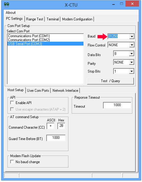
Note: In the LadyAda article, there is a section that explains how to replace the FTDI driver required to program the XBee to work at 31250 bauds-per-seconds. If you use Windows 8, there is no need to do this. When you install the X-CTU program from the XBee maker’s site (Digi.com), Windows 8 will recognize the FTDI chip and allow you to change the baud rate (using the method described in the ladyada article). Then, all you have to do is change the X-CTU program’s baud rate by typing “31250” directly in the Baud field:

and the terminal tab window will let you access the XBee again. This means that it will be easy to change the XBee speed again.

Two AA batteries, an XBee radio and a Midi IN port (using a 6N138 optocoupler)

The circuit in the article cited above is for bi-directional communications, but my version is for uni-directional exchange. I am only interested in sending Midi messages from the instrument to a computer.

NO  processing is done in this circuit. The Midi signal comes in through the Midi cable, enters this circuit (minus the Midi OUT section)…

Thanks Limor!

From ladyada.net (Thanks Limor!)

… and that’s it! The internal XBee circuit takes care of transmission, error correction and synchronization.

The only reason I use an opto-coupler (6N138 in this case) is because I’m using 3 Volts to run the circuit and the Midi IN port, as per the Midi specifications, runs at 5 Volts. So the optco-coupler is used for voltage level matching, not ground loop prevention. The 6N138 can run on 3 Volts, so can the XBee. This means that the circuit can run on a couple of fresh 1.5 Volt batteries (as shown in the picture). Keep in mind that there is NO voltage protection here. Using 3 x 1.5 Volt batteries will fry the XBee (maybe…).

The circuits draws ~50 milli-Amps. Most of it is to power the XBee radio. The 6N138 needs less than 2 mA. So, a batterie pair should last about 50 hours (2500 mA/hour ÷ 50 mA = 50 hours). This is theoretical. The XBee will function down to about 2.8 volts, so the circuit will stop sending Midi messages before the batteries are completely depleted.

I tested the circuit with a single CR2032 batterie and it worked fine. That particular batterie will probably only work for a few hours, but makes for a very compact installation.

On the receiving side, I used another XBee connected to an Arduino and I used an Arduino, a Sparkfun Midi Breakout board,

and a very simple program:

/*
MR-2 V0.1
 2013-1-10 PracticaUsage.com

 Receive data on XBee radio using a Software Serial Port
 then send it all to the Hardware Serial Port
 */

#include

SoftwareSerial xbeeSerial(2,3); //RX,TX

void setup()
{
 Serial.begin(31250);
 xbeeSerial.begin(38400); //can be any speed. XBee receives
 // at whatever speed the other XBee is transmitting
 //Serial.print("MR-1 V01 xBee RCV"); //for debugging
}

void loop()
{
 if (xbeeSerial.available()) { //send on standard Serial
 //anything from xbeeSerial
 //Serial.print(" "); //for debugging
 //Serial.print(xbeeSerial.read()); //for debugging
 Serial.write(xbeeSerial.read());
 }
}

The Arduino will talk to another piece of midi equipment or, using a Midi-to-USB adapter, can be connected to your computer. The Arduino could also be connected directly to the computer through its own FTDI chip/USB Port and a Processing program could digest the data.

Conclusion

The XBee is well built and the error correction algorithm does the job. While testing the circuit above, I had NO stuck note. Every Midi message was received successfully, even when the equipment was using “Running Status” to save data transfer.

One drawback is the 50 mA current used by the circuit. In the next post, I will suggest a few alternatives to put the device to good use.

Posted in Electronics, MP, Music equipment | Tagged , , | 6 Comments

MRe-1: A special version of the MP-1: A Midi Transmitter

A special version of the MP-1 was built to get MIDI data from the Vortex and send it wirelessly to a computer for further processing. I have decided to name it the Midi Remote Emitter 1 (MRe-1).

MRe-1 with a short Midi cable

In fact, the electronics is the same as the MP-1, but the Midi-Out port was not put in, and of course, a special version of the software was used.

The idea is to use an RFM12B radio attached to a Jeenode Arduino compatible board  from Jeelabs to send midi commands. The initial goal was to only send CC commands, but I decided to try and see if I could also send NoteOn and NoteOff commands.

Jeenode with Midi IN port

The software works. The hardware… not so much! The RFM12B is using 915Mhz as a base frequency for communications. This is a general band that is used by alarm systems, weather sensors, etc. The main use of this unregulated band is to send sensor data to a processing unit. In general, if a data packet doesn’t make it to the base, it’s OK. Of course, when using it for an alarm system, you either have to keep sending the signal until it is received or you have to use some error correction processing. So, my idea was to have the unit send most commands without worrying about delivery. This is perfect for repetitive  commands like Volume control or Pitch Bend. But there are situations when you want to be certain that a command is received. For example, Command CC65, Sustain, forces the receiving equipment to hold all notes currently on and any note sent in the future until the same command is received, this time with a value of zero. So, the way I chose to do this was to send an Acknowledgement request from the receiver and resend the command until completion.

The problem starts when a series of commands is sent in rapid succession. For example, it might be OK to miss a NoteOn command here and there (although it can really mess up a piece). But you want to make sure that a NoteOff command is received, because it becomes really upsetting when a random note gets stuck when playing. The traffic can get pretty awful when playing complex pieces and two-handed chords.

I chose to have a three-stage error correction routine:

  • First, send a command and request an Acknowledgement (Ack) and wait for a few milliseconds for an answer
  • If no Ack is received, put the command in a buffer so it can be resent later and keep processing incoming data
  • Every once in a while (but frequently), go through the buffer and resend any command in there. A command only gets erased from the buffer when an Ack has confirmed its reception

There are many parameters to think about here. First, how long can we wait for a command to be Acked before the next one has to be sent. Midi is working at 31250 bps. This is about 32 micro-seconds between each bit. So you’re getting roughly 3,125 bytes per second (serial transmission in 8-N-1 format). This is 1/3 of a millisecond. Since a midi command generally contains 1 to 3 bytes, throughput is, on average, less than 1500 commands per second. Now, thats a lot of notes to play! But remember, your Midi channels also transmits NoteOff, CC, PC, Pitch Bend, AfterTouch, etc. So yes, there are situations when there is too much traffic. Also, the RFM12B is set to transmit at ~49K bps. While it is faster than Midi, my data structure is sending 12 bytes for each incoming Midi command. So, I’m effectively quadrupling the data sent.

So, how long can the program wait for an Ack? I set the period at 5 ms. There is a buffer that can deal with incoming Midi messages and store a few, and I can accept a droped message here and there.

The Ack buffer is set at 16 commands in my program. This means that up to 16 commands can be waiting for a re-transmit at any time. I address the buffer in round-robin mode and remove any command that has been Acked. But to process the buffer takes time, especially if it fills up a bit. In the buffer process, I set the Ack delay to 50 ms. I really want these commands to get out of there.

The main problem is radio interference. As explained in these two posts, the RFM12B is sensitive to radio interference. So much so that it becomes impossible to use error correction and keep the data flow intact.

I have to abandon the RFM12B for now. I will test with XBee radio when I have time.

Posted in Arduino, Electronics | Leave a comment

Alesis Vortex: A better Manual: Functional Description and Midi Programming Guide

This Alesis Vortex User Guide is available as a PDF file.

UPDATE 2013/11/7: Alesis posted a new firmware (1.20) and the Vyzex Patch Editing software on their site. I posted about the changes here. The new Firmware/Software combination kind of makes this page less relevant. I tested the manual programming of the new Firmware (1.20) changes. They are noted in their respective sections: Pitch Wheel, Pads.

In the previous post, I looked at the inside of the Alesis Vortex. This time, I examine the messages coming out of the Vortex and look at the programming of the different switches and sensors.

I decided to write this guide because I kept forgetting how certain buttons were programmed, and because as of this writing (2012/12), Alesis still hasn’t produced a detailed manual. Also because you have to reprogram the Vortex quite often, especially since there is NO way to know what is already programmed, and NO way to save the programs on a computer. Hopefully, Alesis will change this in the future. Continue reading

Posted in Vortex | Tagged , , | 151 Comments

Alesis Vortex – First Review: What’s inside? (Tear Down)

I received an Alesis Vortex today:

Of course, I will do a user review.  I also did a functional review. But first, a tear-down!

(As usual, a click on the picture will enlarge it) I will try to be precise when describing the placement of parts: the Vortex is seen in this picture as a spectator would see it, but the user (musician) will see it in reverse, and upside down! So I will refer to the photos as you see them when pointing left and right (and up and down).

First impressions

The Vortex weighs about 2.5 Kilos (5.5 pounds). Shiny white plastic all around (that will probably hold a nice paint job pretty well). Construction is tight and nothing is rattling. The size is just right. The keyboard is 3 octaves. There are numerous buttons, knobs and switches that I’ll cover in this tear-down. They feel kind of mushy, but it’s the build underneath that will determine their  lifespan. Continue reading

Posted in Music equipment, Vortex | Tagged , , | 26 Comments

Jeenode: Interference

Because of the previous post, I decided to  test a bit more. To see if I could physically move the board to reduce interference. So I connected the Arduino with the attached RFM12B radio module. The one using the Sparkfun MIDI breakout board. As I was clearing the desk, I placed the Arduino on a side table, still attached to the computer via a USB cable.

Suddenly, most of the interference disappeared! The Arduino was receiving the messages from the EM-1 every ~2.5 seconds. I then tried moving the board around. The amount of interference would go up as I got closer to the computer of the computer screen.

I decided to try the same thing with a Jeenode. I could not repeat the situation. Interference was uncontrollable with it.

I tried every different board I had: Arduino Duemilanove, Arduino Uno, LadyAda DC Boarduino. At first, I thought that the FTDI was causing the problem, but the same chip is found on the Arduino. I tried different FTDI cables and boards. I even tried battery power. There seems to be no way to get the Jeenodes to behave! I will have to find out what the differences are between the Jeenode and the other boards.

Posted in Arduino, Electronics | Tagged , , | Leave a comment

RFM12B: Dealing with radio interference

This is a screenshot from the serial monitor of a Jeenode (Arduino compatible) connected to my computer. It runs a program that will listen to incoming radio messages through its RFM12B radio transceiver. In this window, you can clearly see too lines that start with “OK”. These are real messages coming from my EM-1 Energy Monitor. The sending Jeenode is busy calculating energy consumption but manages to output a message every 2.5 seconds, on average. Timing is not critical, so I just let the Jeenode crunch numbers at full speed from measurements coming in from 5 current monitors and output a message when it can.

Whats interesting in that window is the rest of the stuff: GARBAGE! The listening Jeenode is very busy printing incoming messages that it can’t understand. JCW, of Jeelabs, wrote a fantastic library that parses incoming messages to identify those that come from other Jeenodes. It uses preamble bytes and CRC to maximize recognition and reduce error rates. But believe me, the ATMega processor (same as the Arduino) is VERY busy parsing these messages to identify valid ones.

If I turn the Q flag on in the RF12_DEMO.ino program showed in this window, only valid packets are displayed. The Q flag instruct the program not to print the messages, but they still have to be parsed for “real” messages.

This would be ok if there wasn’t so much invalid messages flying around. What happens (and what prompted me to study these results), is that I could see that the receiving Jeenode, tied to a PC that does all the energy calculation and data acquisition, was missing messages from the sending unit. I know that the sending unit does indeed send every ~2.5 seconds. I can monitor the blinking LED on it. It never misses a beat. But the receiver will often miss incoming packets. Sometimes for minutes… Sometimes for an hour… But most of the time, it receives most messages. So I decided to run a few tests.

TESTING … 123

First, I walked around the house with a Jeenode attached to a laptop, using the same monitor window. The interference was pretty consistent around the top and main floor. The basement fared a little better. The number of erroneous messages was definitely lower. Maybe half as much. I thought that there could be a rogue emitter in the house: I use 2 wireless weather station, and my alarm system’s 2 door switches, 1 movement detector and 1 smoke detector all use the same 915 Mhz frequency band.

So, I went outside, with the laptop and Jeenode. Interference was just as bad. I even walked away from the house. No change.

We don’t have neighbours! The closest house is more that half a kilometre away. We live isolated in a field, in the country. So if the garbage doesn’t come from my house, it has to come from somewhere else.

But, there is a transmission tower a kilometre away. A big one, with lots of antennas, many of them transmitting cellular signal, and who knows what else.

So I guess that some of the interference must come from the tower. I will have to take the laptop and go away and try again.

Patch

The only thing that I can do to improve the apparent reception of valid messages is to use a SEND->ACKnowledge communication protocol. JCW has included the necessary software in the RF12 Library for the Jeenodes.

Basically, the sending unit sets a bit in the message header to requests that the receiving unit sends an ACK message back, confirming reception of the messages. If the sending unit doesn’t get the ACK, it will send the same message again. Transmission should eventually complete.

The ACK strategy is only a patch. If the garbage ratio is too high, it could be minutes before the transmission is considered complete. What happens to the other packets then? How do you process messages coming out of order? What happens to battery operated sending units, that will keep retrying and drain the battery quickly with the emitter at full power?

Radio communication is about compromises: For the energy monitor, the compromise is to ignore lost messages. For other projects, like the MP-1, every packet is important, and some are crucial and cannot be ignored. The next post explores the series of compromises needed to make that work.

Posted in Arduino, Electronics, MP | Tagged , , , , | Leave a comment