
The auxiliary pumps on my old California Spa (from 2005) stopped working one after the other over a few (winter) months. I decided to dismantle the control panels that are in the spa. They both seemed water logged and the touch surfaces were all cracked.
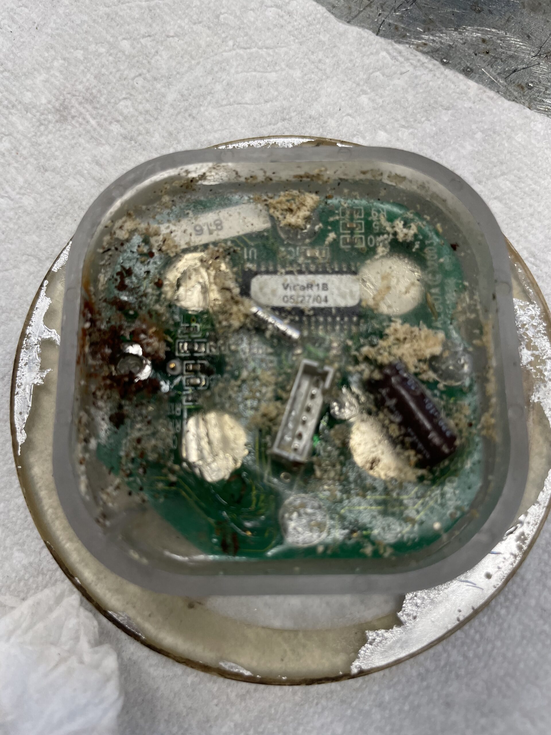
Dismantling the control boards is a mess! they are filled with what looks like unset glue, or unset silicone. That stuff has the consistency of Jello and is VERY sticky! At first, I thought that the control boards were only holding buttons and LEDs. But after cleaning them, I realized that they contained a small micro controller. Maybe it was powered by a standard 5 Volts power supply. I tried to simulate contacts of the buttons (4 of them) but in the end, I had to admit that damage was beyond repairability.
I decided to work on the control circuit box instead. At least I could see the circuit board!
Cal Spa aux pump control box schematic
There are 6 wires connecting the control panel to the control box. Red and black, white, green, blue and brown. I presumed (and measured) that the red and black were + and -. Lucky me: very standard +5 Volts and ground. No idea what the other wires were. I tried measuring voltage, resistance, impedance and all. Still no idea. I was on the impression that the LEDs were controlled by a couple of wires, and the four buttons each had their wire. But if there is a microcontroller, chances are that it’s more complex than this.
I decided to open the control (relay) box, near the pump. The circuit is simple enough: a relay, to handle the 240 Volt line to the pump. A small circuit to provide 5 Volts to the control panel (transformer, a few resistors and capacitors and a LM340 (7805) voltage regulator. A bridge rectifier is attached to the transformers secondary (18 volts). See the first drawings below.

The BROWN wire seems to provide a safety feature for the pump. If it receives 5 volts, it sends it to a TRIAC driver IC (MOS3052 photo isolator) that is attached to the gate of a TRIAC (240V COMMON (white) from the SPA mains through a 180 Ohm resistor to the gate). This will insure safety by cutting the 240V COMMON unless activated.
The BLUE wire is connected to an NPN switching transistor. If it receives 5 volts, it activates the base of the transistor through a 10K Ohm resistor. The transistor will let 5 volts go from the Collector pin (from the power supply above) to the Emitter. A powerful filter capacitor (10K uF) will clean the 5V and send it to pin 1 of a photomos IC (AQV210E) that in turn will let 24V ac go from the transformer to the relay, which connect the 240V LINE (black) wire to the pump. That IC must be very sensitive to line noise to require such a filter capacitor! (update: or maybe my drawing is wrong and the capacitor is filtering the 5V DC right after the voltage regulator, providing a clean supply to everything 5V.)
The green wire is attached to nothing in the control box. The white wire is connected to the green wire from the temperature sensor attached to the exit pipe from the pump (connected to the control box through a separate 3-pin connector) to start the pump if the temperature inside the pipe is close to freezing. I haven’t implemented this feature because I don’t know what kind of signal is sent by the temperature sensor. Probably a variable voltage, but I cannot test this (because summer is coming!).
So, if you connect the BROWN and BLUE pins to 5 volts, it should start the pump. But only as long as the connection is made. Then a momentary contact button will not work. Of course, I could have used a simple switch. But the switch cannot be turned off automatically. One safety feature of this (and many other) spas is that every pump turn off automatically after 15 minutes.
Enters the Arduino!
I needed one with a couple of relays, one for each control box. I am replacing two control panels. I had a LinkNode R4 from years ago at the bottom of the Arduino box.
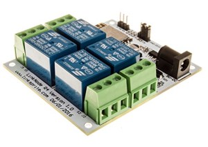

The LinkNode has a clean circuit to drive 4 relays. The onboard Arduino is actually an ESP8266 microcontroller with plenty of power for what I have to do. The circuit uses 4 pins to control the relays. I needed 2 additional pins to read the buttons. So I soldered two wires to pins 4 and 5. The buttons were then attached to these pins to make contact with ground to send a zero to the pins, which were held HIGH by default. I used a relay to close the circuit on each control box. It would connect the BROWN and BLUE wires (twisted and soldered to each other) to 5 volts (RED wire). So I soldered the BLACK and RED wires to the power input pins of the board. By the way, the LinkNode needs about 170 milli Amp to run 2 relays and the ESP8266. The 5 volts circuit in the control box is good for 1000 milli Amp with the 7805 it uses. I used a jumper wire to connect the RED wire to one of the relays. The other relay is not used to power the Arduino, so I just connect the 5v and BROWN/BLUE wires to the second relay. Closing the relay then connects the BROWN and BLUE wires to the RED (5V) wire as needed.
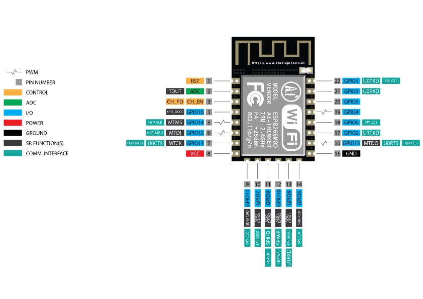
The ESP8266 has many usable pins. Few boards use them all. The LinkNode uses only a few. Here’s the pinout of a standard ESP8266:
Arduino Code
I decided to use pins 4 and 5 for button inputs. The pins on the ESP8266 are referred to as GPIOs (General Purpose I/O). In Arduino code, we use digital pins (normally D1 to D13). When using a standard ESP8266 with no equivalent D pins, all you have to do is use #define macro definitions in the code to refer to GPIO pins.
/*
    Replacement for two control panels for a California Spa to activate
    two auxiliary pumps

    2024-4-29 PracticalUsage.com Initial Version
*/


long RELAY1_start_millis = 0;
long RELAY2_start_millis = 0;
bool RELAY1On = false;
bool RELAY2On = false;

//#define allows the use of original GPIO pin numbers of an ESP8266 board
// instead of Arduino pin number equivalent
// 2 relays and 2 buttons (momentary ON)
#define RELAY1 12
#define RELAY2 13
#define INPUT1 4
#define INPUT2 5

void setup() {

  pinMode(RELAY1, OUTPUT);
  pinMode(RELAY2, OUTPUT);
  pinMode(INPUT1, INPUT_PULLUP);  //Input pins will default to HIGH using the internal pull-up resistor
  pinMode(INPUT2, INPUT_PULLUP);
}

void loop() {

  if (digitalRead(INPUT1) == 0) {      //INPUT1 is pulled down by a momentary switch button attached to pin 4
    if (!RELAY1On) {                   //if the RELAY is OFF, turn it ON
      RELAY1_start_millis = millis();  //save the starting time
      delay(500);                      //lazy, half a second debounce
      digitalWrite(RELAY1, 1);         //then the RELAY is turned ON
      RELAY1On = true;                 //and we set a boolean to indicate the state of the RELAY
    } else {                           //if the RELAY is already ON, turn it OFF
      delay(500);
      digitalWrite(RELAY1, 0);
      RELAY1On = false;
    }
  }
  if (digitalRead(INPUT2) == 0) {  //same logic for the second circuit
    if (!RELAY2On) {
      RELAY2_start_millis = millis();
      delay(500);
      digitalWrite(RELAY2, 1);
      RELAY2On = true;
      //println("RELAY2 ON");
    } else {
      delay(500);
      digitalWrite(RELAY2, 0);
      RELAY2On = false;
    }
  }
  //STOP the pumps automatically after 15 minutes
  // if the time interval since the pump was turned ON is greater than 15 minutes (in milliseconds)
  //  AND the pump is ON (saves a few CPU cycles...)
  if (millis() - RELAY1_start_millis > 900000 && RELAY1On) {
    digitalWrite(RELAY1, 0);
    RELAY1On = false;
  }
  if (millis() - RELAY2_start_millis > 900000 && RELAY2On) {
    digitalWrite(RELAY2, 0);
    RELAY2On = false;
  }
}
The code is compact (for an ESP8266!) and safe.
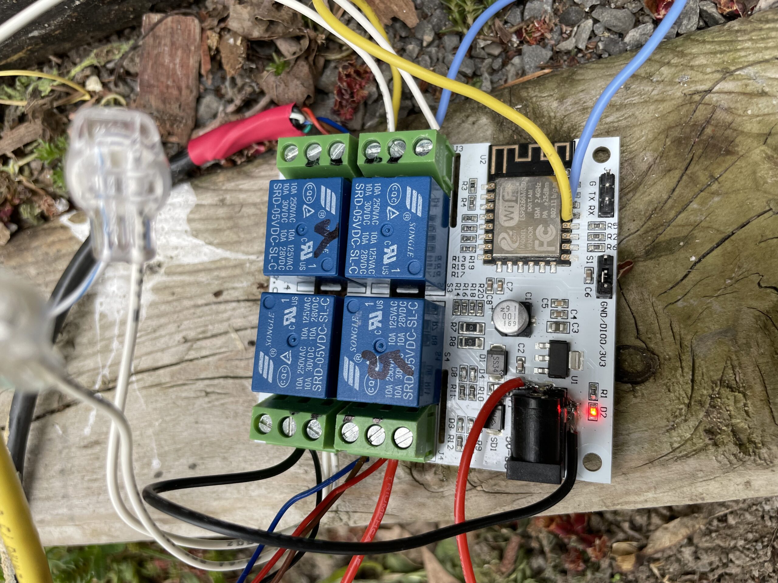
The Arduino is in a water resistant plastic box, connected to the 2 control boxes using the original cables used to connect the control panels to the control boxes. A 4 conductor cable (yellow in the photo) now links the momentary switches to the Arduino. Safety first: The voltage in the Arduino box is 5 volts, and all mains 240V is in the controls boxes, using the original safety features of the circuit.

The control panel momentary switches buttons are waterproof and have been glued using epoxy. The whole panel is glued using silicone “Alien Tape” which prevents water from going behind the panel while being un-gluable for maintenance or futur functions.
Some ideas…
Finishing notes: There is plenty of code space left in the ESP8266 for futur modifications. On the list is activating the Wifi connectivity for remote controlling something. Also on the list is using the 2 relays left on the board to control something else… like LED lights or other niceties! Some functions provided by the original control panels haven’t been implemented, mostly “pulsating” pumps. We never used those functions but a couple more buttons could be implemented if necessary since there are more input pins left unused on the ESP8266.
Leave a Reply