While prototyping the PU-2 and testing a lot of new components to reduce cost and increase performance, I decided to allocate some surplus equipment to a new project: the Energy Monitor.
Basically, the project uses an Arduino (of course) linked to sensors placed in the main breaker box in the basement at the office. The idea came from a stumble upon this site and this other site.
The project involves tapping into the main electrical panel.
This is safe if your keep your hands off ANY metal part, especially the two big connectors at the end of the main black wires. These are connected to the electrical transformer outside. This is a standard north american 200 amps house energy supply for electrically heated house (needed here in the cold white north!). The black wires are coming directly from the outside, and tap in to the meter. If you touch the metal part at the end of the wire, you might receive, depending what else you’re touching:
- nothing: only if you are touching NOTHING else made of metal. NOTHING. You might thing that an innocent looking piece of metal is not connected to anything, but don’t find out the hard way, or you might get…
- 110 volts at 100 amperes if you are touching the white wire or the ground. You can be killed in mere milliseconds.
- 220 volts at 200 amperes if you also touch the end of the other black wire. You can be killed twice as fast.
Any of these can kill rather quickly, or at least “hurt you real bad”. THE WIRES ARE COMING IN BEFORE ANY FUSE OR BREAKER CAN CUT THE CURRENT.
That being said, doing this project is relatively safe, as we are only clipping sensors onto INSULATED wires. My method: I use only one hand, the other being inside the back pocket of my pants, and I concentrate very hard. No distraction! The hand-in-the-pocket method comes from electricity labs when I was in high school. A hand-in-the-pocket will never end up touching a ground or other metal part. Only one hand to concentrate on. It cuts your chances of a mishap by at least 50%.
Notice anything wrong in the picture above? The electrician chose aluminum wires for the mains. Aluminum wires have to be bigger than copper wires for the same amperage. So these black wires are 15.5 mm thick with the insulation. My sensors can only take 14mm. Sad. Of course, I could cut the insulation and clip onto the metal, at 12 mm. But to me, the text in red above is very important. So I have ordered two bigger clips.
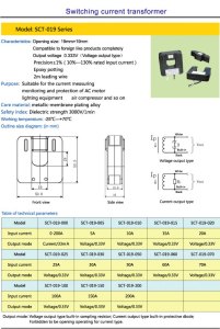
The sensors I’m using are the SCT-013-000, the SCT-013-030 and the SCT-019-000. The differences are that the SCT-013 have a 13 mm opening (actually close to 14 mm) and the SCT-019 have an opening of 19 mm. The last three digits are the amperage rating. The SCT-013-000 is rated at 100 amps, the 030 is rated at 30 amps and the SCT-019-000 is rated at 200 amp. Click on the images to see them full size.
So, the two clips I already had are used to pinpoint particular power outlets. For example, one is monitoring the office space south wall plugs, where all the computers and lab equipment are connected. Another one is monitoring the air conditioning unit, installed on its own breaker. The third one, rated at 30 amps max, is monitoring the hot water heather. They can be re-clipped in seconds.
The two main clips (on order) will be used to monitor the current flowing through the two main wires. These two wires supply 110 volts when measured to ground/zero volts. They supply 220 volts when measured from one to the other.
The three smaller clops will be mobile, used to analyze particular circuits. For example, since the offices are in the country, we often get power outages. I will be able to monitor the generator while the two main sensors will let me know when the power is back on. Also, documenting the electrical signature of the main current eaters in the office will let me get more precision when looking at the main current monitors.
The programming/Arduino part of this project is explained in the next post.


Leave a Reply