Code available on Github.
This project is about replacing a Hot Tub Control Panel for an old California SPA hot tub, using its Balboa electronics and interfacing an ESP32 microcontroller using Wifi and Bluetooth.
The SPA project has evolved. I have an old (2005) CalSPA that needs new electronics. The previous pages were about replacing the main Balboa board. But something more urgent happened. The main control panel, used to display status and control the SPA and situated on top of the hot tub, has started to malfunction. So…

This post is about replacing the control panel.
The panel is pretty standard issue for this type of SPA. The electronics are from Balboa Spa. That includes the main board (see previous posts) and the control panels, used to display information (e.g. Temperature and pump actions) and use control buttons.
There are aftermarket panels available but since the hot tub and main panel are old, 2005, they are “out of stock” pretty much everywhere. If in stock, they are expensive and “non-returnable”. So…
Making a Control Panel for and old California Spa
I was able to find documentation on some projects, notably from netmindz, that is compatible with my Balboa GL9800 control board. This control board is compatible with the GL2000 family of control boards. Others have designed interfaces for newer boards, like cutrer, and also focused on interfaces with Home Assistant.
The SPA uses the RS-485 communication topology to exchange information with the SPA components and control panels. RS485 is well documented and used in industrial environments all over. It is similar to RS422 and others. I have to thank those who have reversed-engineered the SPA communication protocol to figure this out.
Netmindz, and others, have written code to tackle the SPA commands and interface with Home Assistant. Unfortunately, for me anyway, not all communication protocol bits and pieces are (well) documented, and there is few comments in the code. So the user, me, is to rely on this existing code that, in my case, did not work in my environment. I will do my best to explain and document my project and code.
I first built a pair of RS485 nodes using a simple Arduino and programming, with a couple of TI SN75176 chip. It worked, but I want this to live IN the hot tub environment.
I found a premade RS485 ESP32 board on Amazon: The WaveShare ESP32-S3 WS485.

I chose that board because WaveShare built a tough unit with plenty of protection on the communications side. This board uses electrically isolated RS485 interface (same for a CAN interface that I don’t use). The board also uses a clever circuit to enable input voltage in the range of 7-36 Volts. On the WIKI for this board, WaveShare included plenty of code examples. I uploaded that code to start testing the communications with the main board of the SPA. I had also designed my own RS485 interfaces on a breadboard and used an old Arduino to test the initial versions of my code, to develop the code so that I could test messages exchange outside of the hot tub.
The supplied code by WaveShare is great, but not documented. And… it doesn’t really work that well. I was at least able to test the receiving of RS485 data from the spa. So I was certain that netmindz was on the right track.
The ESP32-S3 is a version of the ESP32 with more memory and like most ESP32, it has Wifi and Bluetooth radios. So as a side benefit, my SPA will now have a Wifi communication interface. I don’t mind using physical buttons to control my SPA, and a button box is probably on the way for this project. But having Wifi enabled allows control from anywhere on my network, using a dedicated box (with another ESP32-Wifi) or just a simple iPhone and a web interface. This is the chosen solution.
Wifi also allows me, on an ESP32-S3, to do “over the air” (OTA) software updates, so I don’t have to plug my laptop outside anymore, directly in the microcontroller inside the SPA. That’s my main reason for using Wifi.
On top of this, Wifi enables the ESP32 to use MQTT to exchange information to and from the SPA, with a computer on the network that has much more computing power than the ESP32 and can interface with other systems.
What? No Home Assistant interface?
Although I use home assistant for a few devices that are not HomeKit compatible (and not even Homebridge compatible), I saw no advantage to monitoring my SPA full time, from my main dashboard. Others have done interfaces for HA if you need this.
And then, of course, the ESP32 comes with a Bluetooth radio. I will use Bluetooth to interact with the SPA with an old iPhone that I have when I’m IN THE SPA. The iPhone is a XS model and is kind of waterproof (IP68). I will use this until I install new buttons to replace the existing control panel.
I will also try to have Siri interface with the new Bluetooth interface on the SPA. But Siri is quite temperamental…
Here’s a breakdown of the initial physical setup.
The WS485 connects with the SPA main board with a set of 5 wires: Ground, +9Volts, 485 A, 485 B and Panel Select (see below). I am using an SH1 connector supplied with the WS board to access pin 2 of the ESP32 and use it to receive Panel Select trigger. Any other (free) pin could be used. The plug on the main board is 8 wires but then 3 are not used. The exact plug unit is: Digikey 2147562082

- 1 = 485 A
- 3 = 385 B
- 5 = Panel Select
- 6 = + 9 Volts
- 8 = Ground
I am using a temporary plastic protection box for the new electronics.

The photo above shows the WS485 and my optocoupler board installed in the SPA in a plastic box.

Simple Optocoupler circuit using a 1N648 or equivalent to protect the input pin in the WS485. Might be superfluous as some people report no issues using 5 volt signals. Note: the ground in this circuit is shared with the ground of both the WS485 and the SPA (via PIN 8 of the SPA connector).
About Panel Select
This pin (PIN 5 on the panel) is normally showing 5 volts except when the main panel is expressly talking or listening to your control panel. The SPA main board alternates between all MAIN panels, sending PIN 5 to ground, or low, when addressing a panel. Timing is very important and this is well explained in the code. Because the ESP32 pins are 3.3 Volt, the 5 Volt signal from the SPA on Panel Select might cause a problem. So I designed a signal shifter using an Optocoupler (1N648) that I have used in many other projects. The circuit is described in the comments, in the code library. A resistor voltage divider could also be used. One thing about my circuit is that the presence of 5 volts on the Panel Select pin on the SPA means that the input pin on the other side of the 1N648 is normally LOW, as it is inverted by the optocoupler circuit. It switches to HIGH the the Panel Select goes to 0 volt, or ground. This is explained in the code.
About the communications
The main board sends many messages per second. It adresses (Panel Select or PIN 5 trigger) each panel about 15 times per second. I figured it out by looking at this screenshot (from one of my TEST programs in the code library):

Note: the left column shows time, as in 11:09 and 22 seconds dot milliseconds. As you can see, during the 11:09:22 second, PIN 5 was activated 15 times and the number on the right shows the time PIN 5 was active, in microseconds (2900 or 3600 uS, depending on the message type), every 70 milliseconds or so. So it is ON for 3-3.6 millisecond every 70 ms.
Here’s a more complete typical sequence (from another TEST program):

The main panel sends specific messages like this one:
fa142039374603211208800a386100000ecThis particular message is a series of Hexadecimal pairs (8 bits) and 23 bytes long. There are also 2 other types of messages: one that starts with 0xFB that is 9 bytes long and one that starts with 0xAE that is 16 bytes long.
About type “FA” messages (23 bytes long)
FA messages are showing the status of the SPA/Hot Tub. My predecessors figured out that not all the bytes are carrying useful information. Here’s the breakdown:
fa14203937460003211208800a38610000000000ec
- FA 14 is the message identifier. 2 bytes.
- 20 39 37 46 is the temperature, in ASCII digit format, including the scale identifier (here 46, which is ASCII character “F” for Fahrenheit). In this example, 20 is a “space” character, 39 is the number 9, 37 is the number 7. So the temperature is 97 F. 4 bytes.
- 00 is the PUMPS or JETS information. The first 0 is the status of pump 2 and the second one is the status of pump 1. Here both are OFF.
- 03 is the Heater and Lights indicator. The 0 means the heater is OFF and 3 means the lights are ON.
- 21 is the “state” indicator. Only the 1 or second digit is significant. 1 is “Standard”
- 12 is the “mode” indicator.
- A bit further, byte 14 and 15 are the Time indicator, in hexadecimal
- Then there is a bunch of 0 followed by “ec” which is the control byte (CRC explained below).
I skipped the other bytes that do not contain information that we need in the project (maybe later).
About AE messages (16 bytes)
AE messages are not really treated in this project. I actually don’t know what they are for. I just ignore them in the code.
About FB messages (9 bytes)
These are as important as FA messages. They are sent to the main board and contain “command” information. For example, sending
0xFB, 0x06, 0x64, 0x35, 0x16, 0x00, 0x09, 0xF6, 0x05will toggle the lights, on and off.
The structure of this type of message is
- FB 06 is the message identifier. Always the same. 2 bytes
- 64 35 16 00 is the special code that MY main panel recognizes for valid commands. The main computer expects a specific format for FB commands. To find YOUR specific code, you have to look at the FB strings that YOUR main board sends or receives (with another TEST program). Even when resting, the main board send FB strings constantly. So you just have to “spy” on yours using a test program (many in my Github). 4 bytes.
- 09 F6 is the actual command, here “toggle the lights”. 2 bytes.
- 05 is the CRC (Cyclic Redundancy Code) for the command. To get the particular CRC for each command, you could calculate it (many algorithms exist) but it is simpler to just spy on you SPA by pressing the buttons on another control panel or looking at the default FB messages sent by the main board.
So the first 6 bytes are the same for all commands. The last one is always the CRC. The actual individual command is always 2 bytes long.
I was lucky enough that the existing control panel was still working a bit. (although it needed a good “wack” with a fist or a rubber mallet to wake up.) But I was still able to control the SPA and spy on it for individual commands. If your control panel does not work at all, you can still spy on the main board to figure out the special 4 byte code used by your SPA. You will have to calculate the CRC using the bit of code found in netmindz GitHub. My control panel died as I was finishing this project…
I figured that if I had to send a command to the main board, it had to be while PIN 5 was active right after the reception of an FA message.
Mathematics
In Screenshot 2, you can see the number of messages in the same second (14:13:11) of all three types! (There are about 80 to 96 messages per second!) There are some messages that are not recognized because my test program could not identify the first byte (communication error mostly and because printing on the console is horribly slow).
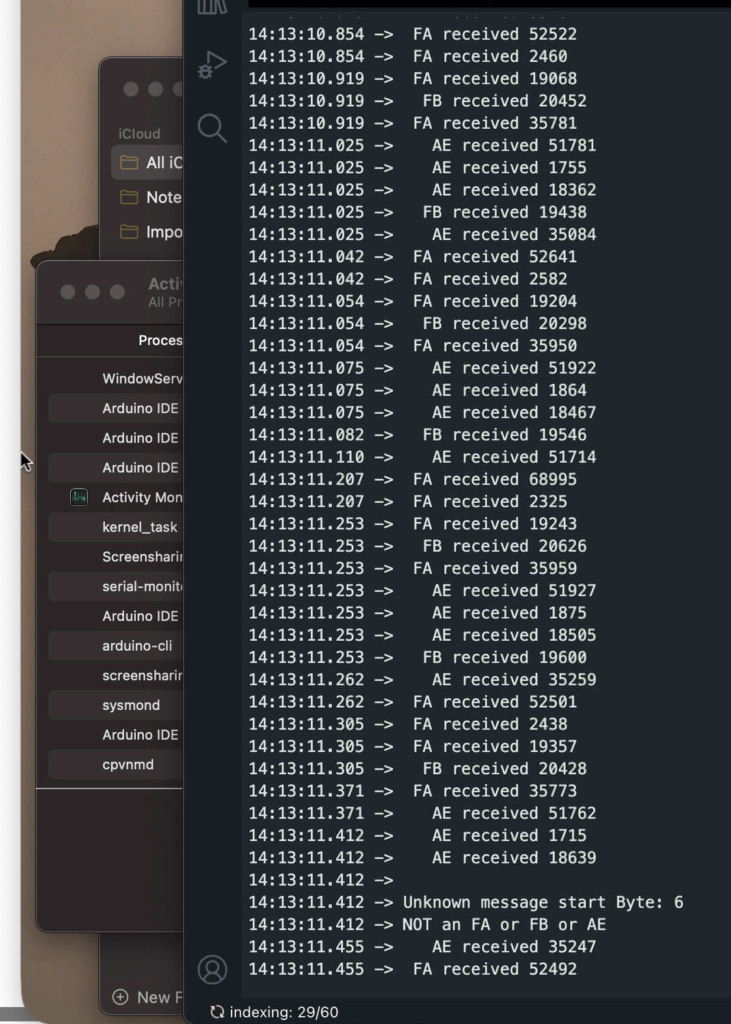
The numbers on the right are microseconds (uS) since PIN 5 (Panel Select) went “low” (to ground). A pattern emerges: The second AE or FA message in each series of 3 has a low number (around 1800-2500 uS). My panel is plugged in the second receptacle on the main board (the existing (malfunctioning and dying) panel is number 1). Then the second FA is mine, I presume.
Let’s do some math. Remember that PIN 5 is active for about 2900 or 3600 uS each time according to Screenshot 1. From studying the message At 14:13:11.207, it indicates the complete reception of an FA message 2325 uS after PIN 5 is triggered (it’s in the code). A bit of calculation here: the Rx-Tx speed of RS485 communication for this SPA is set at 115200 bps (typical for many microcontroller families). Realistically, this gives us about 11520 bytes per second speed (86.81 uS per byte). The FA message is 23 bytes long, so we can assume about 2000 uS from PIN 5 trigger to end of receive of FA message (87 x 23). It makes sense to complete the receive at 2325 uS. So I have the attention of the main board for a bit less than 600 uS and up to 1300 uS before PIN 5 is “closed” (from Screenshot 1). As an aside, the previous message, also type FA, was received 68995 uS after the previous trigger. This corresponds to the calculation from Screenshot 1, for about 70 mS.
Now, there seems to be another trigger just before the next AE message at 14:13:11.253. AE messages are 16 bytes long, so 16 x 87 = 1400 uS and the timer shows 1875. There might be a 300-400 uS delay when the main board sends the messages or when our processor “processes” it. According to RS485 specs, and in particular communication protocols used, processing send/receive exchanges adds a decent uS overhead to communication pairs. By the way again, looking at the milliseconds on the left you might say “but 253 – 207 does not equal 70 mS”. Don’t pay too much attention to the milliseconds counter in Screenshot 2. It is the “timestamp for printing the line on the console” of the Arduino IDE and when producing messages as fast as this series, the ESP32-S3 and Arduino IDE “loose track of time” on the console. But the uS counter on the right is correct.
The main board is talking and listening to me for a short time. So from the FA, received 2325 uS after PIN 5 is triggered, I have around 600 to 1300 uS to respond and send my FB command (per Screenshot 1). FB messages are 9 bytes long, so they need at least 800 uS to send (and acknowledge) to the main board which is more than the 600 uS minimum identified here but perfect for the 1300 uS in the same paragraph. We can then conclude that on Screenshot 1, the PIN 5 triggers lasting 3600 uS are for processing FA-FB message exchanges.
Concluding, When PIN 5 is active and an FA message is received and processed in my code, I have a maximum of 1300 uS to complete the sending of my FB command (if one is ready) or about 800 uS to actually send and about 300-400 uS to “negotiate” and close.
About TIMING
When testing all this, I didn’t have all the calculations above and used a lot of trial and error coding. But eventually, I figured that after completely receiving an FA command, I had to wait just a moment to let the main board flip it’s RTS (Request To Send) pin (and flip the RS485’s) to be ready to receive my FB command.
Sending commands to the main panel is easy but the timing is important. When pin 5 is active, an FA command is received and the program running on the WS485 has to wait about 20 microseconds to send the command in response to the FA state reception. LOTS ans LOTS of testing to find this out. This is where I spent most of my testing time (maybe 100 hours)!
So the command that you want to send has to be stored in a buffer, ready to be sent. It is sent at the exact right microsecond (my program actually tries to send 3 times) and it is accepted by the main board.
The main board will then send a new FA status message confirming the new state of the tub. That’s how you know it worked.
About communication errors
As noted above, each message has a CRC attached to the end. This is to make sure that a message received is “valid”. An algorithm looks at the message when it is sent and “calculates” the CRC. The receiver re-calculates the CRC when receiving the message and compares the result to what is attached to the message.
You can appreciate the effect that an invalid message received by the main board could have a catastrophic effect on the hot tub!
But the only thing sent to the main board are FB commands that are ALWAYS the same for this control panel-main board combination. I obtained the CRC for each command message by spying on another control panel but I could have calculated it just once.
My code does not verify the CRC match for any incoming message. If a message is incomprehensible, my code will ignore it. No harm done.
About MQTT
I use MQTT all over my network to exchange information with IOT things. It was all natural that I would use MQTT to talk to the SPA. I already run an MQTT server for the home.
The program running on the ESP32-S3 sends the necessary information (in production any “new” FA type message). It also receives commands from the MQTT server that are formatted by a Web interface. The MQTT server also hosts Node-Red and I designed a dashboard to interface with the SPA. I used this mostly while testing, but knowing that I can control the SPA reliably from any computer on my network is a bonus if all else fails.
About Bluetooth LE (BLE)
I decided to use bluetooth to control the SPA when I’m in it. I will eventually build an interface with buttons and a display to totally replace the failed control panel, but using BLE enables iPhone communications. Of course, I had to write an iPhone application! I will make the code available but might not “publish” it on the App Store. I might build a little button box with an ESP32 and a battery to replace the phone (that is getting wet at the SPA) and use BLE to send messages to the WS485 that lives in the SPA enclosure.
About the code
The main code that is on Github is the one that I actually use. There are still many “printf” statements that I use when testing. I might remove them to improve speed, but it works just fine now. The code that includes the BLE interface is the cleanest as I use it in production. I think that you could remove or replace functions like MQTT or BLE easily if not needed. It would be very simple to interface with the WaveShare WS485 just by using buttons and a simple display.
The ESP32S3 on the Waveshare board is coupled with a 16Meg memory chip. That is enough memory to load software 10 times as complex as what I’m using and still allow OTA. You could run a Web server on this device!
In the future
I plan to have the ESP32 control another ESP8266 that lives in the SPA. See this project. The ESP8266 is happy and has been running independently for a few years, controlling smaller pumps. There is no particular incentive to play with it… but it’s there! If the main board ever fails, I will keep working on the previous project that you can find on this Web site.
Leave a Reply