About MIDI connections: Identifying the Midi pin numbers

A short article to help identify MIDI pin numbers in all those circuit drawings  and photos on the internet.

The cables and connectors for standard (non-USB) MIDI connections


MIDI connections generally use 5 pin DIN connectors. Two pins carry the MIDI signal; pin 4 is set at 5 Volts and pin 5 is the actual signal pin (set at 5 Volts but goes to zero when a bit is transmitted).

MIDI is generally transmitted using 2 conductor cable. There is a shield and a twisted pair of signal conducting wires (twisted pair reduces external interference). Conforming to MIDI specs, the shield is connected to pin 2 at both ends. I use the CANARE L-2T2S cable to make my own cables if I have to. If you build your own cables, or just use store-bought cables, always test them: continuity is important, but a short can ruin your day! So, test pin to pin continuity (like pin 4 to pin 4 at each end of the cable), but also make sure that no pin is shorted to any other pin (like Pin 4 to Pin 5). In particular, make sure that Pin 2 is not connected to the DIN plug shield (the hard metal part surrounding the pins in the cable connector, also called plug shells). Some manufacturers don’t test this. Yes, I repeat, pin 2 must use the CABLE shield and not the PLUG shield, and pin 2 must be connected at both ends. This article has some more details. The cable is symmetrical.

canare L-2T2S

CANARE L-2T2S showing a twisted pair and braided shield

On a MIDI OUT circuit, Pin 2 is connected to ground as is the female connector shield. Pin 2 must be left NOT CONNECTED in the MIDI IN circuit’s female connector, but the female connector shield IS connected to ground as per the official MIDI specifications. Many circuits leave the female receptacle shield not connected.

Used in this manner, with a standard MIDI cable, the fact that the ground (cable shield) is connected at one end only (MIDI OUT), the cable shield acts as an interference protector. It is important to understand that the MIDI ground (Pin 2) cannot be connected at both ends to prevent ground loops. These might cause hum when equipment share a ground through a signal cable but have separate chassis ground (through their power supply, for example).

Why use 5 pins? Apparently, the designers of MIDI reserved the extra pins for future use, as the MIDI protocol was expected to evolve. They are still unused after more than 30 years (MIDI protocol was invented in the early 1980’s). Why keep the 5 pin connectors? Because they are used on millions of instruments, synthesizers, control and pedal boards, interfaces and computers around the world.

MIDI Pin Numbers

Male connector: Notch at top

Identifying the pins!

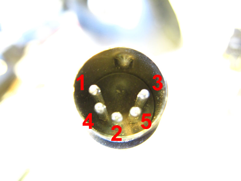
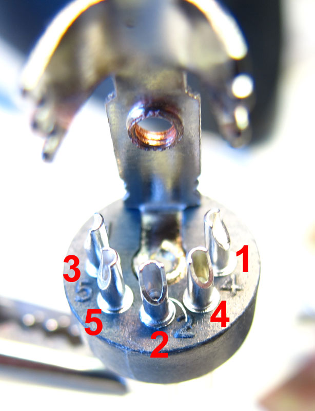
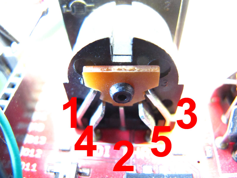
There is often confusion about MIDI pin numbering, so I’m adding a few pictures to help sort things out. RULE OF THUMB: There is a key, or notch on DIN round connectors. Note its position; top or bottom. Pin 2 is ALWAYS directly across from the notch. Pin numbers are NOT CONSECUTIVE. On a MALE connector, only used on MIDI cables, when looking at the pins, pin numbering is COUNTERCLOCKWISE and the first pin is 1. So if the first pin is 1, the only way to apply these 3 rules gives the sequence 1-4-2-5-3. on a FEMALE connector, pin numbering is CLOCKWISE and the first pin is, again, 1.

MIDI circuits on the internet show connectors from the front or the back. To remember if the circuit is showing the connector’s back or front, I use this simple mnemonic: The Face of the Female connector is numbered Clockwise (FFC or, simply, FaCe)

Here’s a few pictures showing pin numbers, front and back:

MIDI Pin Numbers MIDI-in-line-connector-back

MALE (cable) – back

FEMALE (instrument) - front - MIDI Pin Numbers

FEMALE (instrument) – front

FEMALE - back - MIDI Pin Numbers

FEMALE – back


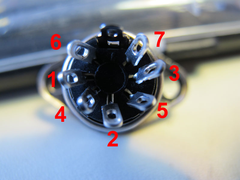
A special case: 7 pin connectors!

The 7 pin connectors are a little special. The first pin is 6. If you remember that, it is still the same general numbering rules.

MIDI Pin Numbers

7 pin FEMALE for panel mount – back

Examples:

Official midi.org electrical specification circuit drawing:

midihw

In the circuit above, the female connectors (this is not a cable) are seen from the back since the numbers are counterclockwise.

In the next circuit, are we looking at the front or back of the connectors?

Midi-board-circuit

Answer: The notch is always across from pin 2. Since this is a circuit, and not a cable, these are female connectors. They are always numbered clockwise from the notch on the FaCe. So we are looking at the face, or front of the MIDI connectors. Note that the bottom connector is showed with the notch at the bottom. But this is still showing the face since the numbers are clockwise. Of course, this circuit is using 7 pin connectors so the first number is 6…

1222062653_fc048d6f12


Finally, another circuit, with no indication of pin number. Can you tell which is which?

If you look at the image above from midi.org, showing the official MIDI electrical specifications, you can deduct that this is a MIDI IN circuit because it has a 4N28 optocoupler.  From the Midi specs, you see that pin 4 is always connected to a 220 Ohm resistor and supplies the 5 Volts to the circuit. Pin 5 always carry the signal and is connected directly to the circuit. Since this is a circuit, not a cable, the connectors are female. Pin 4 is on the right and pin 5 is on the left so this is a counterclockwise pin order. Hence, this is the back of a female connector.


This entry was posted in Electronics and tagged . Bookmark the permalink.

14 Responses to About MIDI connections: Identifying the Midi pin numbers

  1. Luke says:

    I think that your statement, “Pin 2 must be left NOT CONNECTED in the MIDI IN female connector, but the connector shield IS connected to ground.” is dangerous. Or, at least, one hosa cable I’ve tested is. The hosa cable I have has pin 2 (on both ends of course) connected to the shell (outer circle, “connector shield”?) of the connector on one end. The shell isn’t connected all the way through to the shell on the other end, but you can see that if the end that has the shell continuous with pin 2 was connected to an equipment’s input, there would be a ground loop between the two connected devices. I hope this makes sense, and I’m glad I tested all my cables’ continuities before construction of a potentially dangerous device. Other than that, your site was very helpful for understanding the DIN pin orientations. Thanks!

    • rt says:

      I have rewriten the description of cable and circuit connectors to make the distinction between connector shield and cable shield more clear. I hope that this helps. I also added a couple of phrases about the importance of testing the cables to make sure that there is no short between pins and between connector shield and pin 2. I think that your cable is defective. If you measured continuity between pin 2 and the connector shield/shell on your cable (at either end), and that your cable was not connected to any equipment, it is defective.
      As I mention (now) in the article, many circuits leave the MIDI IN female connector shield/shell disconnected.

      I hope that this clarifies the article enough.

      Thanks for the comment, >R.

      • Luke says:

        Yes, I’m sure you’re right. It must be defective. I got it second hand. It looks pristine, so I’m thinking it probably a factory mistake, but you never know. I’ve just labeled that end to make sure I only connect it to an output or thru. I saw that in the midi spec too, but was uncertain the symbolism was referring to the connector shell (shield, nor any other pin is connected to that dashed-line grounded circle, however). Because the shell on input (or output, for that matter) has no electrical function I can see, I doubt it will do any harm to not have it connected. That’s probably what I’ll be doing in my cicuit, at least on input.

        Thanks for the article and clarifications, and you’re welcome for the comment! 🙂

  2. Dragan Minic says:

    Hello, rt.
    Thank you for posting this article. I surely found it very helpful, and learned a lot from it.
    My son is a 15y.o. organist who has just about mastered Bach’s Toccata and Fugue in D minor on two octave pedals connected to a keyboard using a MIDI-MIDI cable. In order to get a better quality sound, I connected the pedals to a computer using a brand new USB-MIDI cable. USB light was on, but MIDI light was not. Several software recognised that MIDI equipment was connected (or perhaps that cable was connected), but none of them produced any sound from the pedals. I have observed that PIN 2 (shield) on the female MIDI OUT connector is not used.
    Could this PIN 2 be the reason for my pedals to work with MIDI-MIDI cable, but not with USB-MIDI? If not, what could be the reason?
    Thank you again, rt.
    Dragan

    • rt says:

      Hello Dragan,
      I can only think that the USB-MIDI device is not working properly. Have you tried it with another MIDI instrument?
      UPDATE: Re-reading your comment, if the software sees the pedals connected to the computer, then your synth software should produce sound. What software are you using?

  3. Rick says:

    What your article is lacking is a finished picture of a complete midi cable, pins exposed, so we can exactly see how BOTH ends of a MIDI cable should be wired, by picture.
    You show a lot of unwired diagrams, but several paragraphs of ‘do this, don’t do that….connect this to the shield of the cable, but not to the #2 pin at one end.” etc.
    Very confusing. EVERY midi cable I have has #2 connected to #2 when tested for continuity, and EVERY midi cable I have does NOT have ANY braided or foil shielding.
    When you cut them open…it’s just five wires, each connected to their respected PIN #’s at each end. Why are all of these cables, from multiple manufactures, nothing at all like the cable wiring diagrams/methods you explain? It’s very confusing when manufactures are NOT doing it your way, and the cables work great.

    You also say that MIDI OUT is diagrammed / wired differently, which can’t be the case, because you can use the same Midi cable for either connection on your keyboard/device….the wiring remains the same….so why is that the case? Thanks in advance.

    Your entire article could be greatly reduced with a pair of colored photographs or diagrams that show a properly wired midi cable, at each end.

    • rt says:

      Hello Rick,

      The article is mostly about wiring in a circuit. That’s where most of the confusion/problems come from.

      All cables should be wired exactly the same at both ends. Of course, pins 4 and 5 are the important ones, carrying the signal. Pin 2 (in the middle) is the ground, and is connected at both ends. So midi cables are symmetrical. To see a coloured picture, take a look at http://www.philrees.co.uk/midiplug.htm , as linked to in my article.

      I have “commercial” cables that use a 5-conductor cable with no shield. They all perform well, most of the time. For short runs (10 feet and less) they work great. I’ve used some 20-feet commercial cables that were a bit sensitive to the environment. I’ve tested some 50-feet cables that did not perform well in my studio, so forget using them on a stage! Your experience might be different.

      I make my cables because I use 7 pins in many of my circuits and 7-pin cables are hard to find (and expensive). Some times, for short runs, I use network cables (8 wires) and solder MIDI plugs at both ends. I’ve tested a 200 feet MIDI cable built that way, on a slightly modified MIDI circuit, and it worked perfectly. I even have an instrument that uses screw terminals for MIDI connections. Actually, I’ve build MIDI circuits that use all sorts of cables, even TRS cables (tough as nails, cheap), XLR cables (same) and cheapo 1/8″ sound cables.

      I also make standard midi cables using the cable described in the article: Canare microphone cable. You can use ANY 3 conductor wire, but interference from other sources (radio frequencies, for example) is better handled with SHIELDED cable, and the shield should be attached to pin2 at both ends of the cable. So when I need a long standard MIDI cable (3 pins active), I make it with SHIELDED microphone cable, as suggested by the MIDI organization, and that Canare cable is tough.

      The notes in my article about the circuit being wired differently for MIDI IN and OUT are correct. Pin 2 is left unconnected at one end, to prevent ground problems. Pin 2 is just used for shielding IN THE CABLE.

      Hope that helps.

  4. Pingback: Web Synth with Particle Photon Part 1: Hardware – Bloop. Click!

  5. Kevin O'Neill says:

    Thank you very much for this article. I put together a simple circuit (with isolation) for plugging an mp3 player into a 1960s Blaupunkt AM/FM/SW. I removed a couple pins from an old keyboard extension cable to try it out but I couldn’t determine if the DIN representation on the schematic solder side or face out. I appreciate your information.

  6. liz says:

    5 wires, 5 pins except #2 pin on midi in, is working for me, also no shield wire used or shell wire used. connected m-audio midi out to Roland S-50 midi as 2nd keyboard (auxiliary keyboard) made 20 foot cable with Ethernet cable, spliced and used pins from old midi tips. thanks for help.

  7. liz says:

    typo sorry

    connected m-audio midi out to Roland S-50 midi in, as 2nd keyboard (auxiliary keyboard)

  8. liz says:

    5 wires, 5 pins except #2 pin on midi in, is working for me, also no shield wire used or shell wire used. connected m-audio midi out to Roland S-50 midi in as 2nd keyboard (auxiliary keyboard) made 20 foot cable with Ethernet cable, spliced and used pins from old midi tips. thanks for help.

  9. Gary says:

    I have a VYPYR 30 amp and need to update the firmware. I’m having a heck of a time finding the correct cable. it is an 8 pin midi to USB. Is a 5 pin male midi with a USB connection going to work, or??

    • rt says:

      First time I see an 8 pin Midi cable! I thought 7 was the maximum. But don’t worry, Peavy Vypyr’s update is done through standard Midi. So you only need a standard 5-pin Midi-to-USB adapter (unless you have another way to connect your PC to Midi equipment). My understanding is that the Midi update on this model is done with SYSEX, a Midi protocol that uses a special Midi format to send bits and bytes between Midi devices. There are quite a few references on my website. So YES, a 5 pin male Midi with a USB connection is going to be OK.
      The firmware is at https://peavey.com/c/Software or do a search on your model in Google.

Leave a Reply

Your email address will not be published. Required fields are marked *