In the previous post, I explained that I temporarily abandoned trying to use the RFM12B radio transceiver to exchange Midi information between two devices.
This post explains how I successfully used the XBee radio transceiver to achieve sending information between a Midi source and a computer.
The XBee radio comes in many different versions. The one I use is the cheapest one, the Series 1. It’s available from Digikey, Robotshop and many, many other suppliers.
Before trying my own version of the bi-directional Midi link, I read this detailed article from LadyAda . You should probably do the same and come back here.
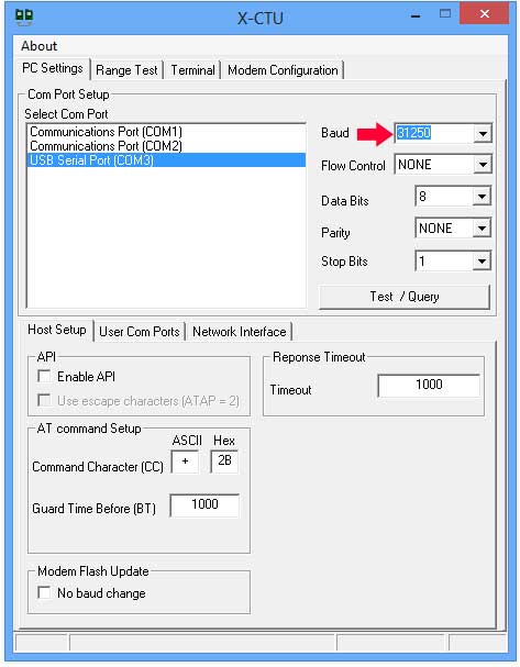
Note: In the LadyAda article, there is a section that explains how to replace the FTDI driver required to program the XBee to work at 31250 bauds-per-seconds. If you use Windows 8, there is no need to do this. When you install the X-CTU program from the XBee maker’s site (Digi.com), Windows 8 will recognize the FTDI chip and allow you to change the baud rate (using the method described in the ladyada article). Then, all you have to do is change the X-CTU program’s baud rate by typing “31250” directly in the Baud field:
and the terminal tab window will let you access the XBee again. This means that it will be easy to change the XBee speed again.

The circuit in the article cited above is for bi-directional communications, but my version is for uni-directional exchange. I am only interested in sending Midi messages from the instrument to a computer.
NO processing is done in this circuit. The Midi signal comes in through the Midi cable, enters this circuit (minus the Midi OUT section)…

… and that’s it! The internal XBee circuit takes care of transmission, error correction and synchronization.
The only reason I use an opto-coupler (6N138 in this case) is because I’m using 3 Volts to run the circuit and the Midi IN port, as per the Midi specifications, runs at 5 Volts. So the optco-coupler is used for voltage level matching, not ground loop prevention. The 6N138 can run on 3 Volts, so can the XBee. This means that the circuit can run on a couple of fresh 1.5 Volt batteries (as shown in the picture). Keep in mind that there is NO voltage protection here. Using 3 x 1.5 Volt batteries will fry the XBee (maybe…).
The circuits draws ~50 milli-Amps. Most of it is to power the XBee radio. The 6N138 needs less than 2 mA. So, a batterie pair should last about 50 hours (2500 mA/hour ÷ 50 mA = 50 hours). This is theoretical. The XBee will function down to about 2.8 volts, so the circuit will stop sending Midi messages before the batteries are completely depleted.
I tested the circuit with a single CR2032 batterie and it worked fine. That particular batterie will probably only work for a few hours, but makes for a very compact installation.
On the receiving side, I used another XBee connected to an Arduino and I used an Arduino, a Sparkfun Midi Breakout board,
and a very simple program:
/*
MR-2 V0.1
 2013-1-10 PracticaUsage.com

 Receive data on XBee radio using a Software Serial Port
 then send it all to the Hardware Serial Port
 */

#include

SoftwareSerial xbeeSerial(2,3); //RX,TX

void setup()
{
 Serial.begin(31250);
 xbeeSerial.begin(38400); //can be any speed. XBee receives
 // at whatever speed the other XBee is transmitting
 //Serial.print("MR-1 V01 xBee RCV"); //for debugging
}

void loop()
{
 if (xbeeSerial.available()) { //send on standard Serial
 //anything from xbeeSerial
 //Serial.print(" "); //for debugging
 //Serial.print(xbeeSerial.read()); //for debugging
 Serial.write(xbeeSerial.read());
 }
}
The Arduino will talk to another piece of midi equipment or, using a Midi-to-USB adapter, can be connected to your computer. The Arduino could also be connected directly to the computer through its own FTDI chip/USB Port and a Processing program could digest the data.
Conclusion
The XBee is well built and the error correction algorithm does the job. While testing the circuit above, I had NO stuck note. Every Midi message was received successfully, even when the equipment was using “Running Status” to save data transfer.
One drawback is the 50 mA current used by the circuit. In the next post, I will suggest a few alternatives to put the device to good use.


Leave a Reply