Alesis iO DOCK: A review

There will be no un-boxing. Sorry, but there isn’t much in the box. Actually, I won’t do much functionality review today. In this first review, I am more interested in what is INSIDE the Alesis iO DOCK.

The Alesis IO Dock

Naked Alesis iO DOCK innards

The left side is for midi connection.Midi in-out and Midi USB. The iO DOCK is core midi compliant, meaning that it will be recognized when you plug it in, without the need for drivers. I will get back to the Midi implementation later.

The rightmost board is the headphone/main volume control and headphone output. They are fed by the multiple op-amp appearing on the right side of the main board.

The main board hosts at least four quad op-amp (3 x MC33079DG and 1 x LM324DG) and a quad voltage comparator (LM339). That, I think, takes care of all the audio ins and outs.

At the top, on the left, just to the right of the yellow video connector, is the footswitch connector. It accepts any old external switch and treats successive presses as a toggle, sending standard midi start and stop signal.

Ah, yes, the video connector. It outputs low quality composite video from the iPad. The quality is ok, for composite. But what is it for? I tested it with YouTube. The video goes out, and the sound is on the output channels. But what does it do besides that? So far, I haven’t found a use for it with music software.

To the left of the yellow composite video is the power supply input and switch. 6 volts, strangely, and at 3 A! That’s a lot of current! The power supply is mandatory, and it will charge your iPad while it’s on.

Down from that area we find the main component: an ARM cortex-M3 CPU (micro-controller) with all sorts of possibilities, including USB interface. It seems to also control Midi communications. I haven’t found a dedicated Midi chip so far ( I have not unscrewed the boards from the plastic case, yet). The big black receptacle at the bottom is a JTAG connector, for programming the micro-controller. Just to the right of this is the USB streaming chip. I’m not certain how it works yet.

There. Good solid construction (10 screws holding the back to the front). Good quality parts (op-amps and all) and plenty of logic and digitalism.

Midi

Back to Midi. When plugged into a Mac using the USB port, the iO DOCK is seen as a standard core Midi interface. So I loaded MidiMonitor (application for the iPad) to see what was going on. The “dock” was recognized and MidiMonitor (application for the Mac) confirmed that midi commands were sent by the “dock” from the application. So I decided to test connection with the PU-2. I used Midi PatchBay to redirect the Midi communication from the PU-2 to the iO DOCK. Bingo. The MidiMonitor on the iPad confirmed communication from the PU-2 through its USB midi port. WOW! This means that you can control software on the iPad from the PU-2’s switches and pedals. Vice-Versa, I could patch the iO Dock s output to the PU-2. All through USB-Midi.

I then proceeded to plug the midi cable from the PU-2 directly into the iO DOCK. That worked too.

One little caveat: the iO Dock documentation specifies that the USB port does NOT do audio. Only Midi at this time. So you have to grab audio from the iO DOCK’s main outputs. Interestingly, the iO Dock is pulling audio from the iPad through its “line-out” connection (of course, since it’s using the Apple Dock connector). It’s also sending line signal to the iPad’s “line-in” connector. The results are signals that are not distorted by the iPad’s op-amped earphone audio path or the mic in. Line in and out are the proper way to treat an audio signal.

Conclusion

This is a keeper. Clean, solid design and the right Midi functionality are in line with the projects I’m working on. The audio quality is OK with me.

I am planning to use the iO DOCK to extend my pedal board’s functions, of course, but I also really like the fact that most Midi and audio apps on the iPad can be used and integrated into the sound path.

Posted in Electronics, Music equipment | Tagged , | Leave a comment

Side Project: Data Stucture – Application

If you were patient enough and read through the two previous posts on this subject, you might be wondering how this applies to the PU-2 pedal board in practice. Even if you were not patient enough, here’s how the data structure will be used:

The data structure was developed to provide a very simple programming interface for the pedal board, using a simple text file format, using CSV conventions (Comma Separated Values). I wrote a short program in Processing that will read the text file and send it to the pedal board, where it will be stored permanently (until overwritten). The processing program is free. In fact, it uses Java as a platform. Java is free and most probably already installed on your computer. The source code will be available on this site by the time the beta pedal board is out.

I wrote a utility program that will read a SySex file used on the Behringer FCB1010. Since the FCB1010 was my starting platform, I figured I could write the code necessary for users to recuperate SysEx file contents, even those created by other programming interfaces. The utility reads the SysEx file and creates a CSV file that is compatible with the PU-2. This way, the user will not have to re-enter previously saved data. I also wrote the code for the PU-2 to directly read SysEx data from a Mac or a PC, but I will only release that code on demand, as the PU-2 will not be using the FCB1010 SysEx format to exchange data.

At this time, the data structure in the CSV file is:

Sequence number, switch number, Midi command type, Midi channel, command, value, comment.

Here’s an example in CSV (just a text file):testdata.csv

If you work on a Mac, Texedit will open the file. You could also open it with Numbers. On a PC, there’s a good chance that Excel will try to open the file right away. The file is a plain text file, but the extension .csv will tickle the computer and it might offer to import it. The fact that the first row is column headers makes all this a lot easier!

I will publish Numbers and .xls files within a few days. Using Excel or Numbers will let me put some validation logic right into the input file. I will do that so you don’t have to send the file to the utility program to test its validity.

Posted in Arduino, FCB1010, Pedal board, PU-2 | Tagged , , , , , | Leave a comment

Side project: Data Stucture – continued

In a previous post, I defined a simple date structure to help in the transfer of the commands sent to/from a pedal board. In this post, I will complete the definition of the data structure and define the physical layer supporting the structure.

Understanding MIDI

“What MIDI Is (from midi.org)
MIDI, which stands for “Musical Instrument Digital Interface,” is a system that allows electronic musical instruments and computers to send instructions to each other.”

The Midi Manufacturer’s association (midi.org) has a nice little booklet about Midi.

Most musicians know about Midi, and many, many, use Midi continuously. I want these musicians to be able to use my pedal boards. I think that my pedal boards should be completely “Midi Obedient”. But, I think that there is a weak spot in Midi. The physical layer. I have not used a piece of Midi equipment that can convey the “what physical control is that command associated with” part. Basically, I think that a Midi commands should be able to transmit a reference to a physical control when necessary.

For example: I have a pedal board with 12 switches. Each one can send one or more commands to software running on a computer. That’s Midi. But I would also like to transfer the switch identifier itself. Midi does not have an easy way to do this. I can use un-reserved Control Change (CC) commands or System Exclusive (SysEx) calls, but the data exchange then quickly becomes complicated. This is what is used today to program the FCB1010 from a computer. Mac and PC versions of programs have been developed by people (who do not work for Behringer) who were tired of trying to program the FCB1010 directly on the board. These programs use SysEx sequences to alter the FCB1010 data. You have to use these programs because SysEx files are hexadecimal, so an interface has to be used to present data to the user and then send it to the Midi device.

If I stick to Midi to program, I have to use SysEx sequences to send programming information. But since I’m using a computer on both sides, why not use something easier?

The Structure Support

The goal is to be able to exchange information between a user (musician), equipment, and computers. The computer part is quite limitless. Using an existing database software, like MySQL, I could easily define tables, databases and all the programs necessary to handle any type of data exchange and storage. On the equipment side, none, that I know of, understand database query languages. On the musician/user, side, some understand databases, some can even program access routines, and some might be comfortable modifying a database content.

But it is all too complex.

That is why, partly, Midi was invented. A “simple” way to exchange information between users and equipment (including computers). Sending and receiving Midi commands is the hardware part of this project. I will try to use standard Midi most of the time, but will need to use fancier stuff too. Actually, “fancier stuff” might end up being easier to use!

My idea is to use simple text files, or CSV files, to exchange data. If you have read the previous post, the conclusion obviously point in that direction. Each “command” is made of a sequence number, effect, switch combination

As a CSV file, this might look like

111,A,1
111,B,1
112,C,2
112,D,2
121,E,3

Although this notation is easy to understand, what will need to happen is a translation to Midi format. Also, it would be easier, I think, to have the physical reference (switch number in this case) second. Our file might actually look like this:

111,1,7,25
111,1,22,0
112,2,7,45
112,2,23,0
121,3,7,90
121,3,24,0

Trust me, this is a lot easier to read than SysEx data!

Here, we have seq number, switch  number, CC command, CC value. So the first line reads: seq number 111, switch 1, CC command 7 (Volume control), volume level 25 (very soft).

This becomes a very easy way to program a pedal board. No fancy interface, just a general knowledge of Midi commands and a CSV editor. If you are reading this post from a computer, any computer, you already have a CSV editor or two. A CSV file is just a simple text file. Oh! wait! A CSV file can also be read an saved from … a spreadsheet program! Chances are that you already have a spreadsheet program on your computer: Excel on the PC, Numbers on the Mac, Open Office Calc on Linux (free). The iPad also has Numbers and many others.

How do we send this to the pedal board computer? This is where the programming comes in. On the main computer side, I use Processing. A simple program reads a CSV file and sends it to the pedal board. The Arduino then stores the commands in EEPROM, its permanent memory.

This is the main code in Processing:

void setup() {
  // Just show an empty square
  size(10, 10);
  background(0);
  stroke(255);
  frameRate(12);

  String [] lines = loadStrings("testdata.txt");// read the file in the current sketch directory
  println("there are "+ lines.length + " lines");
  for (int i=0;i<lines.length;i++) {  // Read each line and process it
    String[] pieces = split(lines[i], ',');  // Cut the line in pieces
    for (int j=0;j<pieces.length;j++) {  //
      print(pieces[j] + " ");  // Do something with the pieces
    }
    //println(lines[i]);
  }
}

Of course, instead of print(pieces…) the final code uses port.write to send the data to the serial port, to the pedal board. With this code, the file can be any number of lines and each line can have a variable number of parameters.

On the pedal board side, the micro-controller has to wait for data to appear on the serial port. Once data is received, it has to be put into a memory “spot” associated with a switch.

Posted in Arduino, Pedal board, PU-2 | Tagged , , | Leave a comment

EM-1: Calculating a burden resistor: an alternate method

I was having trouble calculating the burden resistor necessary for my 5 current sensors. I have 2 200-Amps on the mains coming into the house (I live in north-america), 2 100-Amps floating on different individual breakers and 1 30-Amps also floating.
Each sensor type has a different number of turns on the secondary coil. These figures are not published. I could guess the turn-ratio based on max current output from the manufacturers site. For example, the SCT-013-000 outputs a maximum current of 33 milli-Amp at 100 Amps. In theory. I have two of those, and they have different readings for a given current.

To calculate the burden resistor value for each sensor, I used a known amperage value load, from the reading of a Kill-A-Watt (two 400-Watts lamps) giving me 6.88 Amps.
So for the 200-Amps: I want to be able to monitor total energy usage for the whole house. In my home, each branch coming into the house can supply 100 Amps (for 200-Amps total). I want to maximize the sensitivity on the analog-to-digital pin of the Arduino.  This is the key. If a 100 Amps current passes through the sensor, I want the analog pin to read 1024 (this is the maximum value that an analog pin can report, at 5 volts. The circuit suggested in these pages uses a voltage divider (two 10K resistors). So if no current passes through the sensor, you can expect to read 512 on the analog pin. To measure this reading on the analog pin, I used this piece of code in my energy monitor program:

tmpRead = analogRead(analog-pin-for-this-sensor);
if(tmpRead > maxRead)
maxRead = tmpRead;
Serial.print(maxRead);

where tmpRead and maxRead are integers

Since I want to measure a maximum of 100 Amps, I use 6.88/100 * 512 = 35. So I should choose a resistor that will give me a reading of 547 on the analog pin. Let’s look at the formula:

D = Amp / max-Amp * analogRead(no-load)

or

know-amp-value-from-Kill-a-watt / maximum-amperage-expected-on-this-wire * mid-range-point-from-voltage-divider. So, in this case, a deflection of 35 on the analog pin corresponds to 6.88 Amps on the wire, related to an expected maximum of 100 Amps.

In practice, using the code above, I choose an analog pin and measure the idle value with any burden resistor (try any between 50 and 1000 Ohm). The value on the analog pin (maxRead above) should be close to 512 but can vary because of resistor precision in the voltage divider). I then use a known amperage (hence the Kill-A-Watt) and read the analog pin again. I choose a resistor that will give me a deflection of 35 (for my sensor) using a simple division.

As you can see, this is independent of the type of sensor used. Of course, you have to plan to measure a maximum amperage within the range of your sensor, and I would recommend a safety margin so you don’t overload the analog pin.

Posted in EM-1 | Leave a comment

Side Project: Defining a Data Structure

This is a very long, wordy post. It is that way because it starts with a wordy description of terms. But the goal of the post is to present a simple data structure to define timing, effects and switches that can be used by musicians and equipment to program command streams to send to equipment. Feel free to to the the conclusion and read more about the data structure itself.

I want to be able to send any number of several types of commands when a switch is pressed on my pedal board. Let’s look at the structure of the data for a particular board.

There is always a finite number of switches/pedals/controls. The PU-1 has 9 switches, two expression pedals (variable values), and one rotary encoder. These define the physical layer of the data structure.

Each switch can be assigned any number of commands. This is the action layer of the data structure.

Each command/switch association can be executed is any order, according to the intention of the user. This is the timing layer of the data structure.

Some existing implementations are using terms like “concert”, “set”, “pieces”, “tunes” to define the various timing elements of a performance. I want to avoid terminology confusion by using a simple data structure. Let’s look at a familiar and simple example:

EXAMPLE

A guitarist is starting a concert with a tune called “for simplicity’s sake”. He starts playing a rhythm using a “low level, crunchy” effect. He the switches to a “stighly louder, velvety” effect. The guitar solo starts. The guitarist switches to a “clean loud” sound. He then “adds a strong reverb effect with a delay”. The guitarist goes out of solo mode, alternatively playing the first and second effects defined above until the end of the tune.

Then, the second tune starts. It’s called “give me a brake”. The guitarist starts with an easy rhythm, using the same “low level, crunchy” effect. His solo part calls for a “strident, 2 octave up, distorted” sound. After the solo, it’s back to the first sound until the end of the tune.

If we look at the data structure behind this, we can simplify it by using a more logical notation, like:

for simplicity's sake
   beginning
      low level, crunchy
      slightly louder, velvety
   Solo
      clean loud
      add strong reverb and delay
   End
      low level, crunchy
      slightly louder, velvety

give me a brake
   Beginning
      low level, crunchy
   Solo
      strident, 2 octave up, distorted
   End
      low level, crunchy

This notation makes timing more evident. We can follow the sequence of events easily. Let’s add some formal notation:

1. for simplicity's sake
   1.1 beginning
      1.1.1 low level, crunchy
      1.1.2 slightly louder, velvety
   1.2 Solo
      1.2.1 clean loud
      1.2.1 add strong reverb and delay
   1.3 End
      1.3.1 low level, crunchy
      1.3.2 slightly louder, velvety

2. give me a brake
   2.1 Beginning
      2.1.1 low level, crunchy
   2.2 Solo
      2.2.1 strident, 2 octave up, distorted
   2.3 End
      2.3.1 low level, crunchy

Looking at this, one could easily sort a list of “commands” and play everything in the right order. Timing can then be expressed as an ordered (sorted) list of events, and although order is important, there is no real-time reference.

Each action in our list can be identified too. Let’s rewrite our example like this:

1. for simplicity's sake
   1.1 beginning
      1.1.1 A.B. low level, crunchy
      1.1.2 C.D. slightly louder, velvety
   1.2 Solo
      1.2.1 E. clean loud
      1.2.1 F,G. add strong reverb and delay
   1.3 End
      1.3.1 A,B. low level, crunchy
      1.3.2 C,D. slightly louder, velvety

2. give me a brake
   2.1 Beginning
      2.1.1 A,B. low level, crunchy
   2.2 Solo
      2.2.1 H,I,J. strident, 2 octave up, distorted
   2.3 End
      2.3.1 A,B. low level, crunchy

This way of looking at the sequence of events allows us to identify actions, or changes in the sound during the performance. Actions are not an ordered list and their timing is given by the numbers in front of them. Actually, in our example, you can see that certain effects are repeated more than once (as A and B are).

Lastly, if you are a musician given the list above, you will want to know which switch to press to change the effects. You want to know the location, the exact spot. Lets re-post that list again, with an indicator showing the physical reference of each necessary change in sound:


1. for simplicity's sake
   1.1 beginning
      1.1.1 A,B. S.1 low level, crunchy
      1.1.2 C,D. S.2 slightly louder, velvety
   1.2 Solo
      1.2.1 E. S.3 clean loud
      1.2.1 F,G. S.4 add strong reverb and delay
   1.3 End
      1.3.1 A,B. S.1 low level, crunchy
      1.3.2 C,D. S.2 slightly louder, velvety

2. give me a brake
   2.1 Beginning
      2.1.1 A,B. S.1 low level, crunchy
   2.2 Solo
      2.2.1 H,I,J. S.2 strident, 2 octave up, distorted
   2.3 End
      2.3.1 A,B. S.1 low level, crunchy

Now, we can look at this list and know exactly when, what change in sound will be produced by pressing where.

WHEN, WHAT, WHERE (CONCLUSION)

Let’s go through the beginning of the first tune again. At time 1.1.1, we want effects A and B to be activated by pressing switch S-1. If we remove the text, we get

when, what, where, description

1.1.1,A B,S.1, “low level, crunchy”

or, in a more conventional format:

Using this notation is actually a little bit more involved than what is presented here. Examples will be presented in a subsequent post. Also note that the structure is totally arbitrary. Instead of A & B, the effects in the “what” column could be 1-2, or 1.2, or  1&2. The switches could use letters or numbers, etc. The way each “effects” is defined is also arbitrary. AB might as well be just A, where A is one effect, producing the two sub-effects.

Posted in Arduino, Pedal board, PU-2 | Leave a comment

EM-1: The microcontroller/programming part

This is the actual electronics for this project:

Here’s the theory.

The idea is  that you first need a reference voltage to compare your sensor readings to. The voltage at the street varies a bit, and the voltage inside a building varies a bit more, depending on demand and other factors. In our case, the lowest on record is 106 volts and the highest is 122 volts. Since the circuit and program generally calculate power as a function of both current and voltage (P = V*I) then you want to make certain that the voltage is known.

The electrical circuit is quite simple. I used the calculation and circuit on the openenergymonitor.com site. Thanks for sharing, Trystan.

The schematic for the voltage divider is

Click on it!

where R3 and R4 are 10 K Ohms and R1 and R2 are 100 Ohms and 1 K Ohms respectively. C1 is 10 uF. Basically, R3 and R4 take the voltage from the Arduino power supply, 5 volts, and divide it by 2. R1 and R2 take the voltage from the transformer (about 10 volts in my case) and divide it by 10 (1000/100), giving about 1 volt. So, the Arduino analog pin reads a voltage that varies from 2.5 volts – 1 volt to 2.5 volts + 1 volt, or 1.5 to 3.5 volts. This rough circuit has plenty of safety margin, and a simple program can tell the Arduino to transform this varying voltage into usable data.

Next we need to measure current (the flow of electricity at a given moment) with sensors. The current sensors are made of a circular (or square) ferrite core around which a transformer is wound (from very fine wire). The “laws of electrical current flow” are such that when an amount of electricity flows through (current) a ferrite (or any magnetic-permeable metal) loop, a wire wound around the ferrite loop will be “excited” by a proportional current. For this to work, the source current has to be alternating. This is exactly what we have in most places around the world, alternating 60 times per second in parts of the world, and 50 times per second in other parts of the world.

The number of turns in the wound coil determines the output current induced by the main current. For example, 3000 turns effectively divides the source current by … 3000. So, if the current in the red wire is 100 amps, the current induced into the secondary winding will be around 33 mA (100/3000 = .033).

The same voltage divider is used to provide 2.5 volts for input, but the burden resistor has to be calculated for the given sensor. The burden resistor effectively transform the current output of the sensor into a readable voltage sent to the Arduino. Many sensors do not need the burden resistor. They contain an equivalent transformer that acts as a transistor.

In my case, the voltage divider made of the two resistors that provide 2.5 volts with the electrolytic condenser providing noise filtering is shared between the sensors. The voltage divider (100/1000) and burden resistors are calculated for, and assigned to, a single sensor/analog pin.

I think that my theoretical knowledge makes sense, and measurements concur. I will test a different version that uses the Arduino 3.3v output as voltage source.

I’m using a prototyping board for the moment.  I’m using multiple sensors of different type (current generator and voltage generators) but they all share parts of the circuit. The transformer on the right is from my FCB1010. When I replaced the brain, the power supply became redundant. The Arduino in the PU-2 is powered by a standard 9 volt supply (or a 7-12 volt battery) or directly from a USB port at 5 volts.

The Arduino Code

I use an Arduino, of course. The idea is to measure analog data from the sensors and calculate Voltage, Amperage and different Power numbers. I based my code on Trystan Lea’s code. I actually blatantly copied it and then modified it a bit.

The Processing Code

I wanted to be able to read/process the information coming in from the Arduino. I linked the Arduino to a file server running Linux using a USB cable. The Processing code receives the information over the serial port.

The first step is to prepare the data on the Arduino. As mentioned, I use Trystan’s libraries and code. But I added the part to format the data:

  Serial.print(ch1.Vrms);
  Serial.print(",");
  Serial.print(ch2.Irms);
  Serial.print(",");
  Serial.print(ch2.apparentPower);
     Serial.print(",");
  Serial.print("|");

So, I’m sending numbers (voltage, current and apparent power values) separated by commas with a pipe character “|”(ASCII 124) to mark the end of the string.

On the computer, a simple program written in Processing wait for the data, effectively waiting for a “|”, and then processes it.

import processing.serial.*;

Serial myPort; 

PFont myFont;
float var1, var2, var3;

void setup() {
  size(400, 200);
  myFont = createFont("Arial", 18);
  textFont(myFont, 18); 

  println(Serial.list());
  //Get data from arduino through first USB port
  myPort = new Serial(this, Serial.list()[0], 57600); 

  //buffer input from arduino until "|" character
  //then call serialEvent
  myPort.bufferUntil(124);//Ascii value for "|"
}

void draw()
{
  background(0);
  fill(255);
  textFont(myFont, 18);
  //Show values in the box
  text("Volt: " + var1, 10, 50);
  text ("Amp: "+var2, 10, 70);
  text ("Power: " + var3, 10, 90);
}
//read the feed from Arduino in Processing
//Called automatically because of the "bufferuntil" statement
void serialEvent(Serial myPort) {

  String myString = myPort.readString();
  if (myString != null ) {
    //   myString = trim(myString); //remove whitespace around our values
    String inputs[] = split(myString, ',');
    //now assign your values in processing
    if (inputs.length == 4) {
      var1 = float(inputs[0]);
      var2 = float(inputs[1]);
      var3 = float(inputs[2]);
      print(var1+" ");
      print(var2+" ");
      println(var3+" ");
    }
  }
}

The code waits for a trigger using “bufferUntil()” and then calls serialEvent() which cuts the received string into pieces and then prints them on the console as it prints them inside the box.

The final version uses Pachube.com. It sends messages to Pachube requests so that the whole planet can see how inneficient my office power consumption is.

Posted in Arduino, EM-1 | Tagged | 2 Comments

EM-1: New project – Energy Monitor

While prototyping the PU-2 and testing a lot of new components to reduce cost and increase performance, I decided to allocate some surplus equipment to a new project: the Energy Monitor.

Basically, the project uses an Arduino (of course) linked to sensors placed in the main breaker box in the basement at the office. The idea came from a stumble upon this site and this other site.

The project involves tapping into the main electrical panel.

This is  safe if your keep your hands off ANY metal part, especially the two big connectors at the end of the main black wires. These are connected to the electrical transformer outside. This is a standard north american 200 amps house energy supply for electrically heated house (needed here in the cold white north!). The black wires are coming directly from the outside, and tap in to the meter. If you touch the metal part at the end of the wire, you might receive, depending what else you’re touching:

  • nothing: only if you are touching NOTHING else made of metal. NOTHING. You might thing that an innocent looking piece of metal is not connected to anything, but don’t find out the hard way, or you might get…
  • 110 volts at 100 amperes if you are touching the white wire or the ground. You can be killed in mere milliseconds.
  • 220 volts at 200 amperes if you also touch the end of the other black wire. You can be killed twice as fast.

Any of these can kill rather quickly, or at least “hurt you real bad”. THE WIRES ARE COMING IN BEFORE ANY FUSE OR BREAKER CAN CUT THE CURRENT.

That being said, doing this project is relatively safe, as we are only clipping sensors onto INSULATED wires. My method: I use only one hand, the other being inside the back pocket of my pants, and I concentrate very hard. No distraction! The hand-in-the-pocket method comes from electricity labs when I was in high school. A hand-in-the-pocket will never end up touching a ground or other metal part. Only one hand to concentrate on. It cuts your chances of a mishap by at least 50%.

Notice anything wrong in the picture above? The electrician chose aluminum wires for the mains. Aluminum wires have to be bigger than copper wires for the same amperage. So these black wires are 15.5 mm thick with the insulation. My sensors can only take 14mm. Sad. Of course, I could cut the insulation and clip onto the metal, at 12 mm. But to me, the text in red above is very important. So I have ordered two bigger clips.

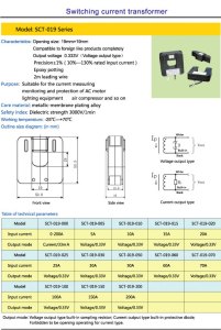
The sensors I’m using are the SCT-013-000, the SCT-013-030 and the SCT-019-000. The differences are that the SCT-013 have a 13 mm opening (actually close to 14 mm) and the SCT-019 have an opening of 19 mm. The last three digits are the amperage rating. The SCT-013-000 is rated at 100 amps, the 030 is rated at 30 amps and the SCT-019-000 is rated at 200 amp. Click on the images to see them full size.

So, the two clips I already had are used to pinpoint particular power outlets. For example, one is monitoring the office space south wall plugs, where all the computers and lab equipment are connected. Another one is monitoring the air conditioning unit, installed on its own breaker. The third one, rated at 30 amps max, is monitoring the hot water heather. They can be re-clipped in seconds.

The two main clips (on order) will be used to monitor the current flowing through the two main wires. These two wires supply 110 volts when measured to ground/zero volts. They supply 220 volts when measured from one to the other.

The three smaller clops will be mobile, used to analyze particular circuits. For example, since the offices are in the country, we often get power outages. I will be able to monitor the generator while the two main sensors will let me know when the power is back on. Also, documenting the electrical signature of the main current eaters in the office will let me get more precision when looking at the main current monitors.

The programming/Arduino part of this project is explained in the next post.

Posted in Arduino, EM-1 | Leave a comment

PU-2: how many presets?

I’m working on the data structure for the FCB1010/PU-2. I’m wondering if there should be a set number of presets per switch or pedal.
One way to implement the presets is to define a number, say 10, and decide that this is the maximum number of “effects” for a particular switch in a “bank”.
Another way is to develop a flexible data structure that allows the user to keep adding patches to any switch.
Let’s look at the first way in detail:
Pros

  • Simple programming
  • Simple data transfer – known dimension of data arrays

Cons

  • “wasted” data space for unused command slots
  • Limited number of effects per switch

The flexible data structure:
Pros

  • Flexible
  • No defined limits implies no waste

Cons

  • much harder to code

What sould an entry contain?

I’m trying to identify as many different types of actions possible from one particular switch or pedal. So far, I identified:

  1. Midi Note
    1. Note On
    2. Note Off
  2. Midi Controller Change
    1. Stompbox mode
    2. Standard mode
    3. Momentary mode
  3. Midi Program Change
  4. Midi SysEx commands
  5. DMX/VCS commands
    1. Implementation of the DMX/VCS protocols
  6. OSC commands
    1. For communication with computers and other devices
  7. Expression Pedals generally send CC commands. Can also send Note commands. Expression pedals should be able to control more than one effect at any time.

For each one of the basic commands, more than one option should be available:

1. Midi Note

Sending a Midi Note command is straightforward. Some controllers don’t send Note Off. Instead, a Note On with a velocity of zero is sent. Also, it is good practice to send midi commands type only once, i.e. if a series of Note On commands are sent, the first one will be a full command, with the subsequent notes sent as values only.

2. Midi Controller Change, or Continuous Controller: CC Commands

CC commands form the real traffic coming out of a Midi controller. CCs are used for everything, from changing instruments to controlling effects. In fact, many CC commands don’t have pre-defined meanings and are left to manufacturers and/or programmers to arrange. In standard mode, a CC command is sent when a switch is pressed. Actually, many CC commands can be sent when a switch is pressed. Each time a particular switch is pressed, the CC commands are resent. In stompbox mode, a command (or series of commands) is sent when the switch is pressed. The next time the user presses the same switch, the command(s) sent are interpreted as a cancellation signal for whatever had been activated on the previous press. In momentary mode, the press of a switch sends a command(s) interpreted as ON, and releasing the switch sends an OFF signal or equivalent.

3. Program change

Straightforward. A switch press sends one or more program changes (called “patch” or “preset” in some software).

4. Midi System Exclusive: SysEx commands

Midi SysEx commands are sent and received to exchange information that cannot be conveyed by other Midi commands. They all have a specific “header” and all end with the hexadecimal value F7. But between the header and the end of the command, the SysEx can contain any number of any hexadecimal value (well, any value smaller than 0x80). Every manufacturer uses SysEx. I was able to exchange SysEx information with a few devices around here. There is no “standard” way to process SysEx.

The PU-2 will not use System Exclusive commands to exchange configuration information. Since most of the configuration is done on a computer (Mac/Linux/PC), the USB connection allows simpler data exchange. I might leave SysEx routine in the firmware for compatibility purposes.

5. DMX and VCS commands

DMX (Digital Multiplex) and Midi VC (Visual  Control) will be integrated in the next major firmware release.

6. Open Sound Control: OSC communications

From the osc.org website: “Open Sound Control (OSC) is a protocol for communication among computers, sound synthesizers, and other multimedia devices that is optimized for modern networking technology. Bringing the benefits of modern networking technology to the world of electronic musical instruments, OSC’s advantages include interoperability, accuracy, flexibility, and enhanced organization and documentation.”

It is my intention to integrate the OSC protocol in the next firmware version.

7. Expression Pedals

Expression pedals are an integral part of many instruments and control equipment like pedal boards (like the PU-1 and the PU-2!).

But… how many presets?

The first firmware persion (V1.x) will process items 1,2,3,4 and 7. Basically sending and receiving any Midi command. How about any midi commands? My intention is to allow the user to store ANY number of presets in the PU-2, or actually, up to filling the entire memory of the micro-controller. That’s a lot of commands! With the micro-controller that I’m using for the prototype, I could store 33,000 commands. If this is not enough, I can also add more memory by using inexpensive EEPROM modules.

Posted in Arduino, FCB1010, Pedal board, PU-2 | Tagged | Leave a comment

PU-2: adding a display

The fcb1010 has a numerical display made of 3 digits. It also utilizes a series of LEDs to give more info about its current state. At best, this is an arcane way of doing things, like trying to program a computer using a old rotary telephone. At its worst, it does make you hate the FCB1010.

I will be writing a Mac/PC/Linux interface as I go along, but certain functions are better accomplished on the device itself (very few!)

During prototyping, I will be using an alphanumeric display, made of 2 lines by 16 characters each. I’m debating whether to add a numerical display, either a simple one similar to the one used now on the FCB1010, or a useful one like the one below. Adding the display is trivial, but expensive.

This display, form an old Digitech GNX3000, is ideal: 8 alpha-numeric 14-segments digits and 2 contrasting numerical digits. The entire display can be run from a single chip… but that chip costs 20$, in quantities of 25! Add 15$ for the set of digits…

Driving a 3 digit display, directly from the Arduino using a serial interface and one digital pin can be done for 13$.

Posted in Arduino, Pedal board, PU-2 | Tagged , , | 7 Comments

PU-2: PIN assigments and some testing

It’s good to have a Mega! Plenty of pins for the prototype. Some of the digital pins are hidden by the shield I made for the connectors.

As far as coding goes, programming the PU-2 is easier than programming the PU-1. The switches are all assigned to an independent digital pin. Each can effectively be debounced in software. The FCB1010 switches are all tied together on one side. The other contact of each switch is tied to a digital pin. Defining that pin as INPUT and doing a digitalWrite on it turns on the internal pull-up resistor of the Arduino:

Be careful about which pin is turned into INPUT or OUTPUT, otherwise you will short them.

  int switchMinus16 = 35;
  pinMode(switchMinus16, OUTPUT);
  digitalWrite(switchMinus16, LOW);
  int switchMinus712 = 52;
  pinMode(switchMinus712, OUTPUT);
  digitalWrite(switchMinus712, LOW);

  for(int j = 0; j <= 11; j++){
    pinMode(switches[j], INPUT);
    digitalWrite(switches[j], HIGH);

For the prototype, I decided to limit the parts count. All LEDs are tied to one 330 ohms resistor that is connected in series with +5 volts.

The code below just defines the pins as OUTPUT and then, as a quick test, lights each LED for 250 ms. Then, the pin is set to HIGH, so the LED is turned off. The digital pin is, in effect, supplying GROUND to the LED when low, creating a simple +_resistor_LED_- circuit.

  for(int i = 0; i <= 11; i++){ // LED pins as OUTPUT
    pinMode(led[i], OUTPUT);
    digitalWrite(led[i], LOW);
    delay(250);                // Just a quick test to see
    digitalWrite(led[i],HIGH); // If everything is working
  }

Note that you can’t (or shouldn’t) turn more than one LED on at a time. As a test, I have used the “persistence of vision” (POV) principle with good results:

digitalWrite(pin1, LOW); // Turn LED1 on
digitalWrite(pin1, HIGH);// then off
digitalWrite(pin2, LOW); // Turn LED2 on
digitalWrite(pin2, HIGH);// then off

If the code is fast enough, you eyes won’t see the LEDs blink.

Posted in Arduino, FCB1010, Pedal board, PU-2 | Tagged , , , | Leave a comment